(15) Install the propeller shaft with the installa-
tion reference marks aligned.
(16) Tighten the companion flange bolts to 108
N·m (80 ft. lbs.).
(17) Install the brake drums.
(18) Install wheel and tire assemblies and lower
the vehicle.
(19) Check the differential housing lubricant level.
DIFFERENTIAL
REMOVAL
(1) Remove the axle shafts.
(2) Remove RWAL/ABS sensor from housing.
NOTE: Side play resulting from bearing races being
loose on case hubs requires replacement of the dif-
ferential case.
(3) Mark the differential housing and the differen-
tial bearing caps for installation reference (Fig. 19).
(4) Remove bearing threaded adjuster lock from
each bearing cap. Loosen the bolts, but do not
remove the bearing caps.
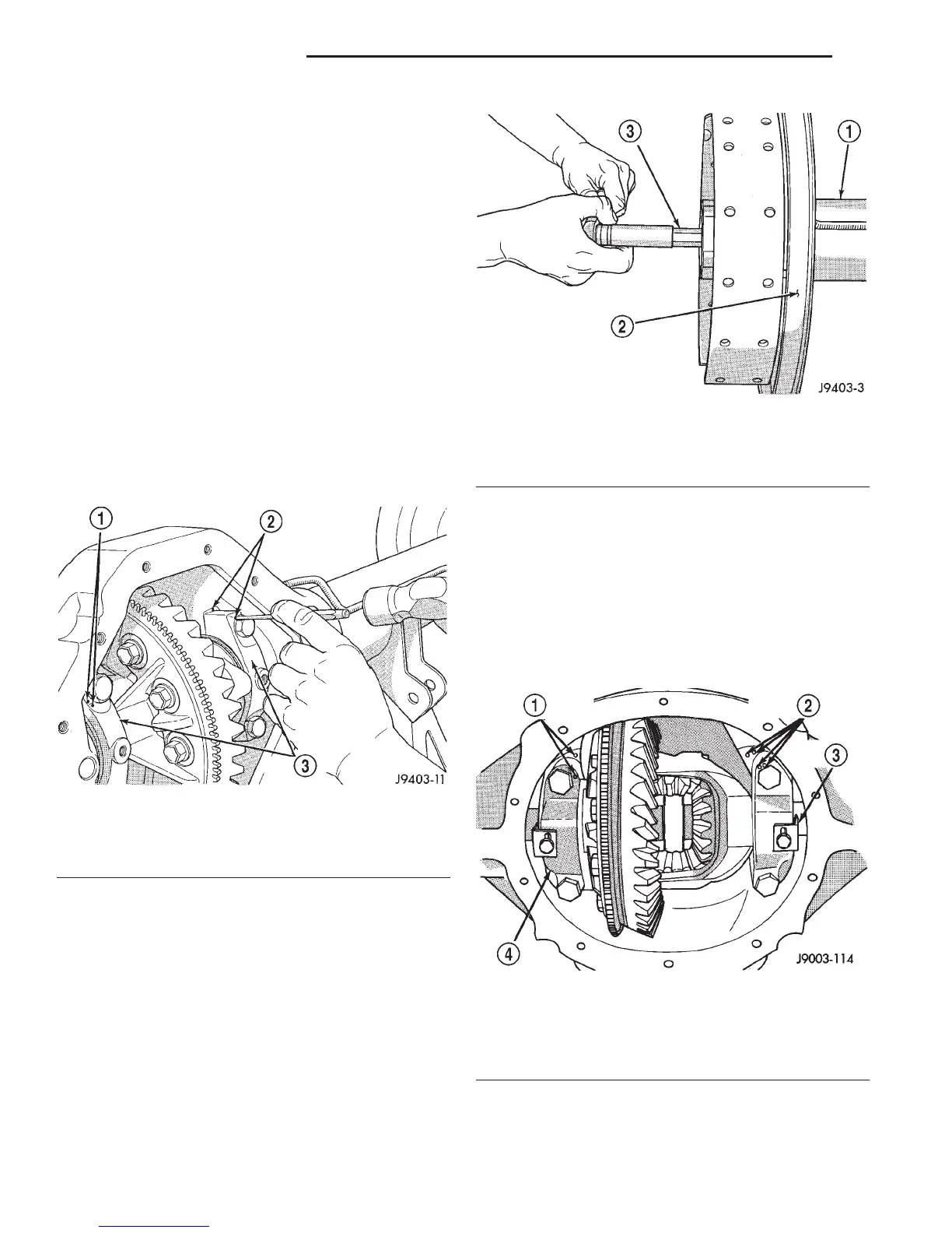
(5) Loosen the threaded adjusters with Wrench
C-4164 (Fig. 20).
(6) Hold the differential case while removing bear-
ing caps and adjusters.
(7) Remove the differential case.
NOTE: Each differential bearing cup and threaded
adjuster must be kept with their respective bearing.
INSTALLATION
(1) Apply a coating of hypoid gear lubricant to the
differential bearings, bearing cups, and threaded
adjusters. A dab of grease can be used to keep the
adjusters in position. Carefully position the assem-
bled differential case in the housing.
(2) Observe the reference marks and install the
differential bearing caps at their original locations
(Fig. 21).
Fig. 19 Mark For Installation Reference
1 – REFERENCE MARKS
2 – REFERENCE MARK
3 – BEARING CAPS
Fig. 20 Threaded Adjuster Tool
1 – AXLE TUBE
2 – BACKING PLATE
3 – TOOL C-4164
Fig. 21 Bearing Caps & Bolts
1 – INSTALLATION REFERENCE MARKS
2 – INSTALLATION REFERENCE MARKS
3 – ADJUSTER LOCK
4 – BEARING CAP
3 - 74 8 1/4 AND 9 1/4 AXLE DN
REMOVAL AND INSTALLATION (Continued)