(4) Remove the differential side gears and thrust
washers.
ASSEMBLY
(1) Install the differential side gears and thrust
washers.
(2) Install the differential pinion gears and thrust
washers.
(3) Install the pinion mate shaft.
(4) Align the hole in the pinion mate shaft with
the hole in the differential case and install the pinion
mate shaft lock screw.
(5) Lubricate all differential components with
hypoid gear lubricant.
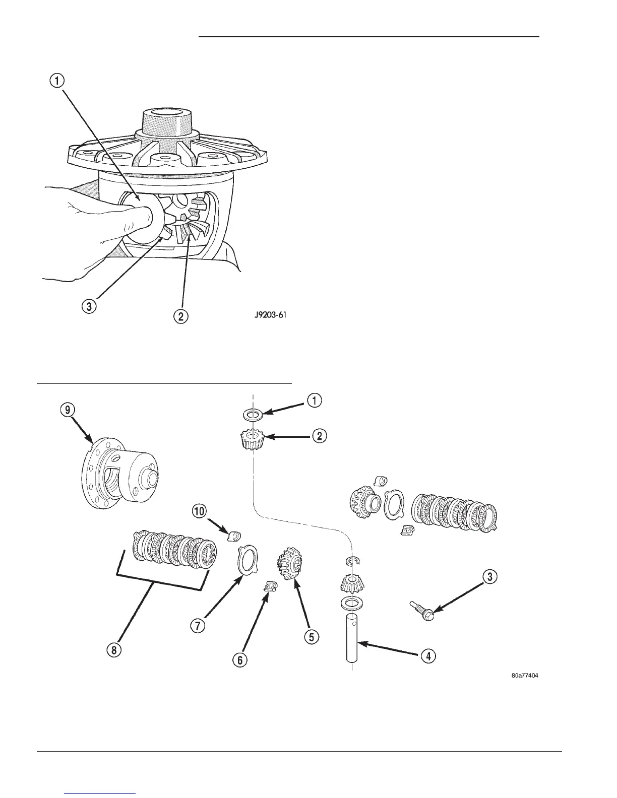
8 1/4 TRAC-LOKY DIFFERENTIAL
The Trac–loky differential components are illus-
trated in (Fig. 43). Refer to this illustration during
repair service.
DISASSEMBLY
(1) Clamp Side Gear Holding Tool 8138 in a vise.
(2) Position the differential case on Side Gear
Holding Tool 8138 (Fig. 44).
(3) Remove ring gear, if necessary. Ring gear
removal is necessary only if the ring gear is to be
Fig. 43 Trac–lok
Y
Differential Components
1 – THRUST WASHER
2 – PINION
3 – SHAFT LOCK SCREW
4 – PINION MATE SHAFT
5 – SIDE GEAR
6 – RETAINER
7 – DISC
8 – CLUTCH PACK
9 – DIFFERENTIAL CASE
10 – RETAINER
Fig. 42 Pinion Mate Gear Removal
1 – THRUST WASHER
2 – SIDE GEAR
3 – PINION MATE GEAR
3 - 82 8 1/4 AND 9 1/4 AXLE DN
DISASSEMBLY AND ASSEMBLY (Continued)