is the amount (in thousandths of an inch) the depth
varies from the standard depth setting of a pinion
marked with a (0). The next two numbers are the
sequence number of the gear set. The standard depth
provides the best teeth contact pattern. Refer to
Backlash and Contact Pattern Analysis Paragraph in
this section for additional information.
Compensation for pinion depth variance is
achieved with select shims. The shims are placed
behind the rear pinion bearing (Fig. 74).
If a new gear set is being installed, note the depth
variance painted onto both the original and replace-
ment pinion. Add or subtract the thickness of the
original depth shims to compensate for the difference
in the depth variances. Refer to the Depth Variance
chart.
Note where Old and New Pinion Marking columns
intersect. Intersecting figure represents plus or
minus the amount needed.
Note the painted number on the shaft of the drive
pinion (–1, –2, 0, +1, +2, etc.). The numbers repre-
sent thousands of an inch deviation from the stan-
dard. If the number is negative, add that value to the
required thickness of the depth shims. If the number
is positive, subtract that value from the thickness of
the depth shim. If the number is 0 no change is nec-
essary.
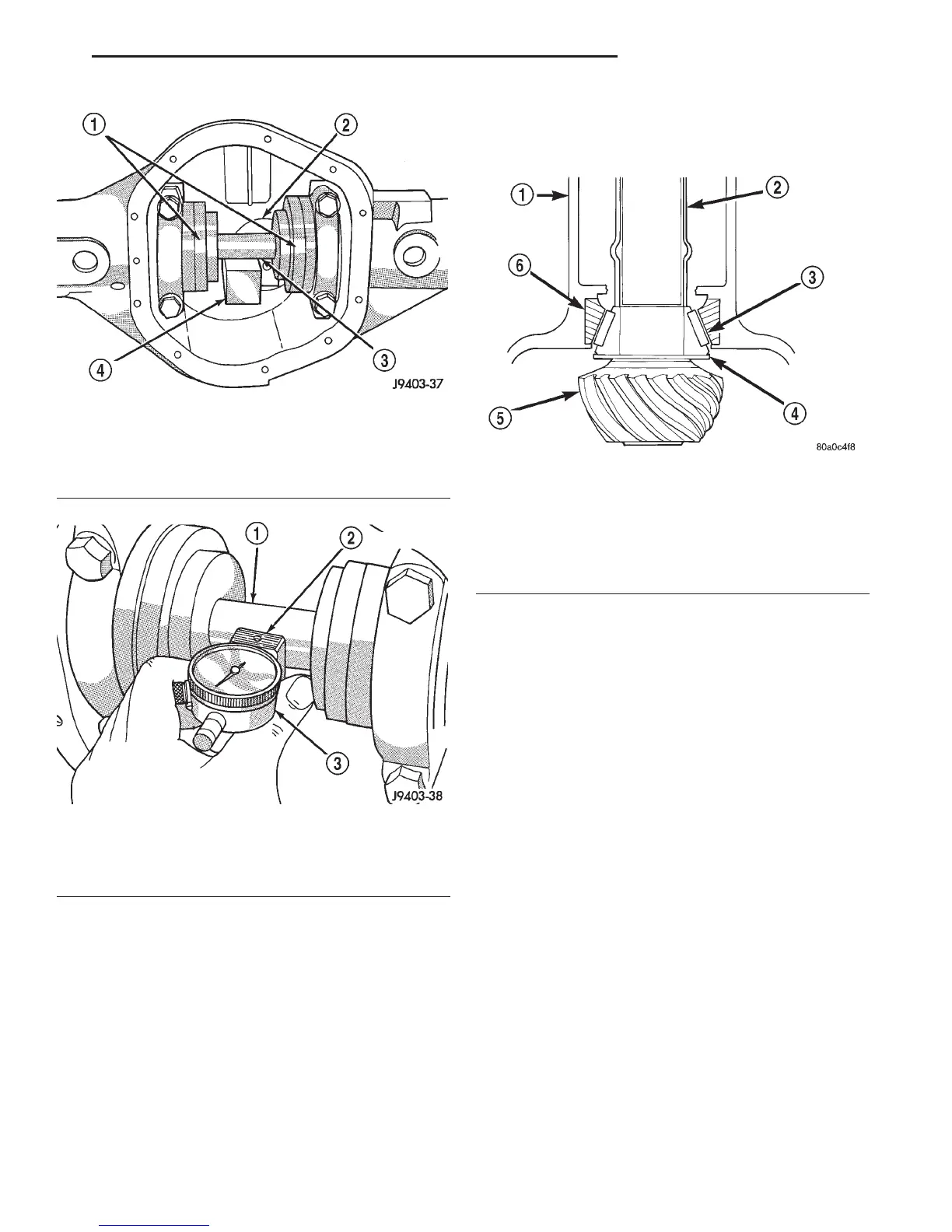
Fig. 72 Gauge Tools In Housing
1 – ARBOR DISC
2 – PINION BLOCK
3 – ARBOR
4 – PINION HEIGHT BLOCK
Fig. 73 Pinion Gear Depth Measurement
1 – ARBOR
2 – SCOOTER BLOCK
3 – DIAL INDICATOR
Fig. 74 Shim Locations
1 – AXLE HOUSING
2 – COLLAPSIBLE SPACER
3 – PINION BEARING
4 – PINION DEPTH SHIM
5 – PINION GEAR
6 – BEARING CUP
DN 8 1/4 AND 9 1/4 AXLE 3 - 93
ADJUSTMENTS (Continued)