RWAL COMPONENT LOCATION
DESCRIPTION
COMPONENT LOCATION FUNCTION
RWAL CONTROLLER Driver side inner fender on a
bracket.
Tests, monitors and controls the
rear brake system.
HYDRAULIC CONTROL UNIT/
RWAL VALVE
Driver side inner fender on a
bracket.
Modulates hydraulic pressure to
rear brakes during an RWAL stop.
REAR WHEEL SPEED SENSOR Top of the rear axle housing. Sends an AC voltage sinewave to
the CAB whose frequency is
proportional to vehicle speed.
EXCITER RING Ring gear inside the differential
housing.
Used to pull the magnetic field
across the wheel speed sensor’s
windings.
RED BRAKE WARNING LAMP Instrument cluster. Indicator for park brake
engagement, hydraulic brake
malfunction, or RWAL malfunction.
AMBER ABS WARNING LAMP Instrument cluster. Indicator of an RWAL malfunction.
BRAKE WARNING LAMP DIODE Instrument panel harness near the
parking brake switch.
Isolates the park brake switch circuit
from the CAB for proper red brake
warning lamp operation.
ISOLATION AND DUMP VALVE
FUSE
Inside the CAB. Fail-safe device for unwanted
control of the isolation and dump
solenoid/valves
ISOLATION AND DUMP
SOLENOID/VALVES
Inside the HCU/RWAL valve. Used to modulation hydraulic
pressure to the rear brakes during
an RWAL stop.
CONTROLLER REAR WHEEL ANTILOCK
BRAKES
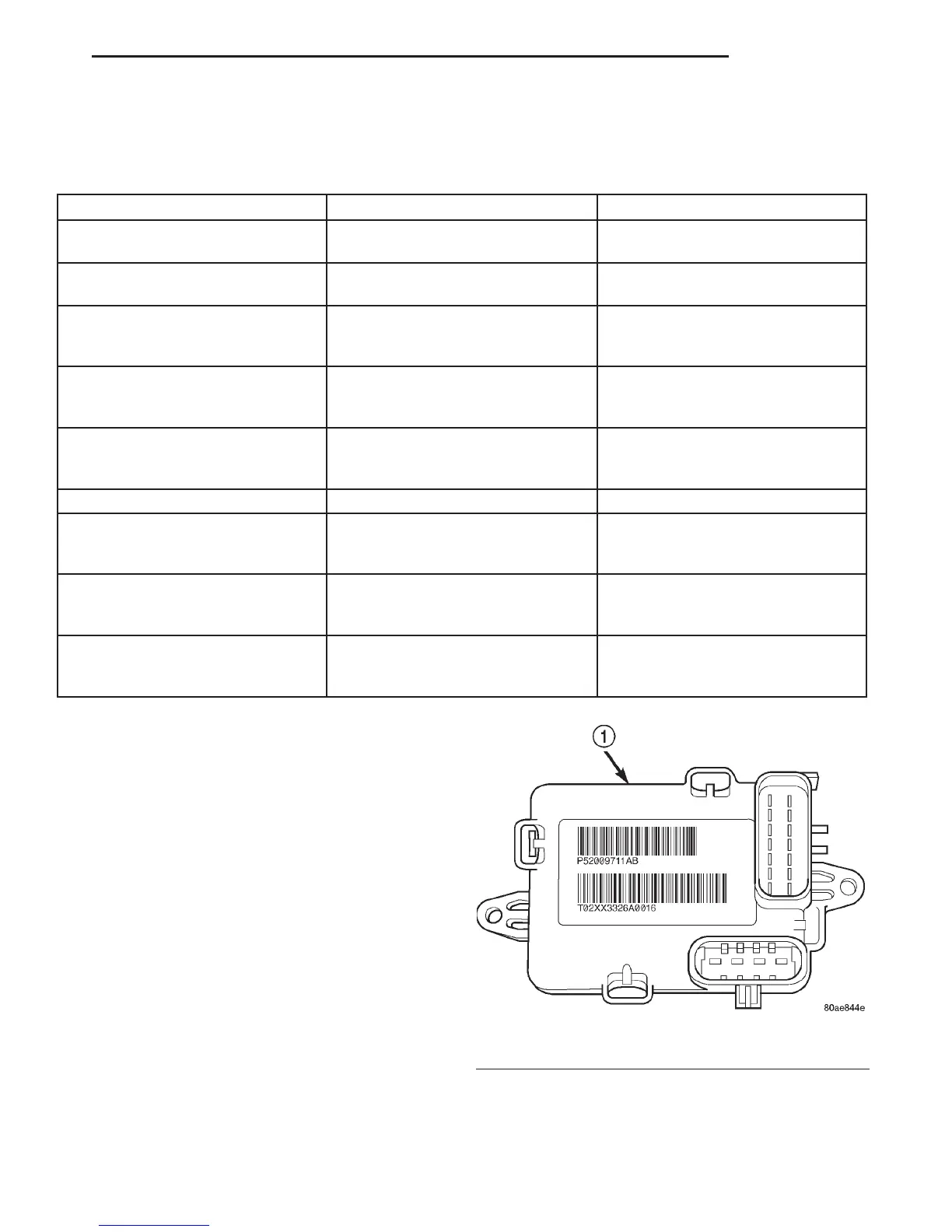
DESCRIPTION
The Controller Antilock Brakes (CAB) is a micro-
processor which handles testing, monitoring and con-
trolling the ABS brake system operation (Fig. 1). The
CAB functions are:
• Perform self-test diagnostics.
• Monitor the RWAL brake system for proper oper-
ation.
• Control the RWAL valve solenoids.
NOTE: If the CAB needs to be replaced, the rear
axle type and tire revolutions per mile must be pro-
gramed into the new CAB. For axle type refer to
Group 3 Differential and Driveline. For tire revolu-
tions per mile refer to Group 22 Tire and Wheels. To
program the CAB refer to the Chassis Diagnostic
Manual.
Fig. 1 RWAL CAB
1–RWALCAB
DN BRAKES 5 - 33
DESCRIPTION AND OPERATION (Continued)