INSTALLATION
(1) Connect harness to sensor. Be sure seal is
securely in place between sensor and wiring
connector.
(2) Install O-ring on sensor (if removed).
(3) Insert sensor in differential housing.
(4) Install sensor shield.
(5) Install the sensor mounting stud and tighten to
24 N·m (200 in. lbs.).
(6) Install the brake line on the sensor stud and
install the nut.
(7) Lower vehicle.
EXCITER RING
The exciter ring is mounted on the differential
case. If the ring is damaged refer to Group 3 Differ-
ential and Driveline for service procedures.
SPECIFICATIONS
TORQUE CHART
DESCRIPTION TORQUE
ABS Assembly
Bracket bolts ........ 14-15 N·m (10-12 ft. lbs.)
Mounting Nuts .......... 12N·m(102 in. lbs.)
CAB Screws ......... 4-4.7 N·m (36-42 in. lbs.)
Brake Line Fittings ....... 19N·m(170 in. lbs.)
Wheel Speed Sensors
Front Sensor Bolt ........ 21N·m(190 in. lbs.)
Rear Sensor Bolt ....... 22.5 N.m (200 in. lbs.)
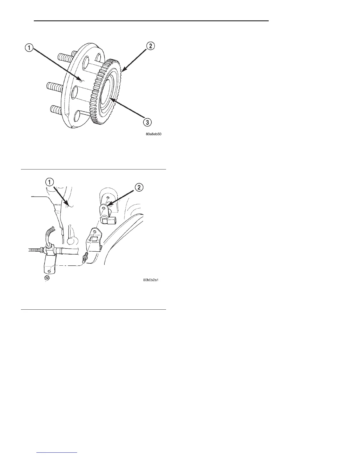
Fig. 12 Tone Wheel 4x2
1 – HUB
2 – TONE WHEEL
3 – BEARING
Fig. 13 Rear Speed Sensor Mounting
1 – DIFFERENTIAL HOUSING
2 – WHEEL SPEED SENSOR
DN BRAKES 5 - 47
REMOVAL AND INSTALLATION (Continued)