WATER PUMP BYPASS HOSE—5.2L/5.9L
ENGINES
REMOVAL WITHOUT AIR CONDITIONING
(1) Partially drain cooling system. Refer to COOL-
ING SYSTEM—DRAINING and FILLING in this
Section.
Do not waste reusable coolant. If solution is clean,
drain coolant into a clean container for reuse.
WARNING: CONSTANT TENSION HOSE CLAMPS
ARE USED ON MOST COOLING SYSTEM HOSES.
WHEN REMOVING OR INSTALLING, USE ONLY
TOOLS DESIGNED FOR SERVICING THIS TYPE OF
CLAMP, SUCH AS SPECIAL CLAMP TOOL (NUMBER
6094) (Fig. 38). SNAP-ON CLAMP TOOL (NUMBER
HPC-20) MAY BE USED FOR LARGER CLAMPS.
ALWAYS WEAR SAFETY GLASSES WHEN SERVIC-
ING CONSTANT TENSION CLAMPS.
CAUTION: A number or letter is stamped into the
tongue of constant tension clamps (Fig. 39). If
replacement is necessary, use only an original
equipment clamp with matching number or letter.
(2) Loosen both bypass hose clamps (Fig. 38) and
position to center of hose. Remove hose from vehicle.
INSTALLATION
(1) Position bypass hose clamps (Fig. 38) to center
of hose.
(2) Install bypass hose to engine.
(3) Secure both hose clamps (Fig. 38).
(4) Fill cooling system.
(5) Start and warm the engine. Check for leaks.
REMOVAL WITH AIR CONDITIONING
If equipped with A/C, the generator and A/C com-
pressor along with their common mounting bracket
(Fig. 40) must be partially removed. Removing gener-
ator or A/C compressor from their mounting bracket
is not necessary. Also, discharging A/C system is not
necessary. Do not remove any refrigerant lines from
A/C compressor.
WARNING: THE A/C SYSTEM IS UNDER PRESSURE
EVEN WITH ENGINE OFF. REFER TO REFRIGER-
ANT WARNINGS IN GROUP 24, HEATING AND AIR
CONDITIONING.
(1) Disconnect battery negative cable.
Fig. 38 Hose Clamp Tool—Typical
1 – HOSE CLAMP TOOL 6094
2 – HOSE CLAMP
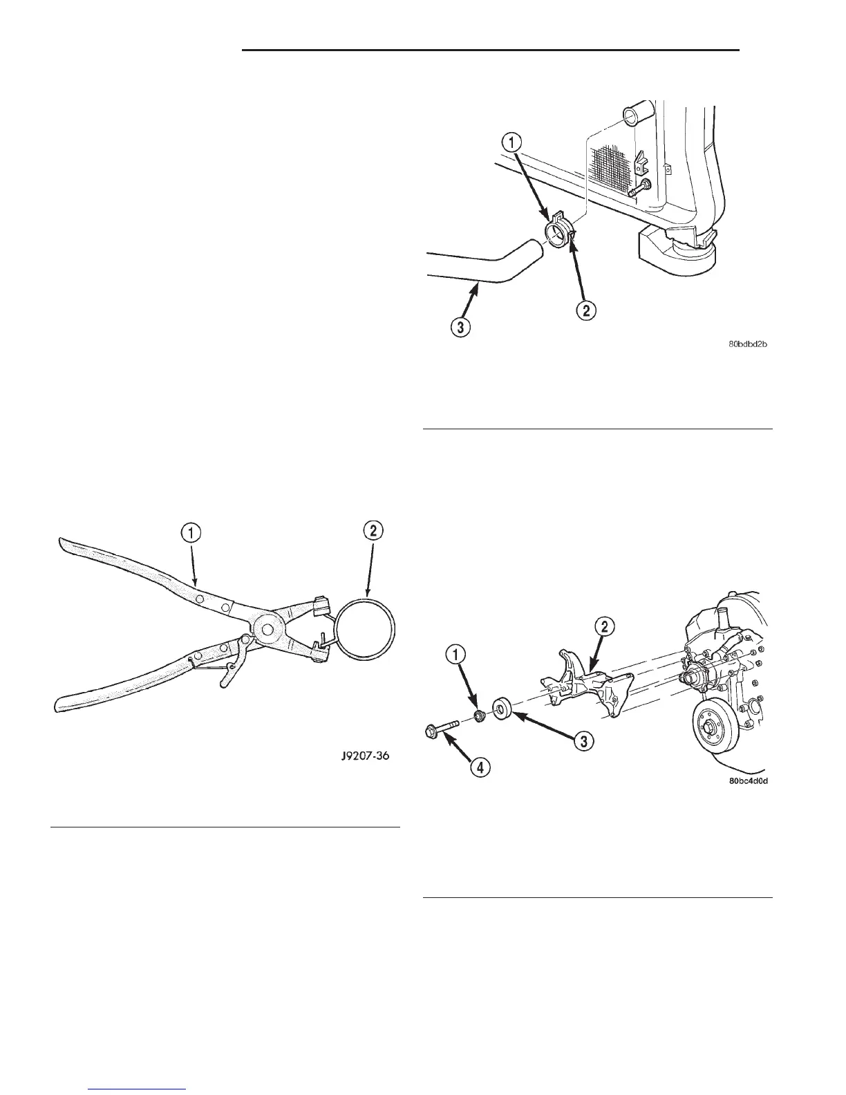
Fig. 39 Clamp Number/Letter Location
1 – CONSTANT TENSION HOSE CLAMP
2 – CLAMP NUMBER/LETTER LOCATION
3 – HOSE
Fig. 40 Generator—A/C Compressor Mounting
Bracket—5.2L/5.9L Engine
1 – IDLER PULLEY BUSHING
2 – A/C AND/OR GENERATOR MOUNTING BRACKET
3 – IDLER PULLEY
4 – SCREW AND WASHER
7 - 30 COOLING SYSTEM DN
REMOVAL AND INSTALLATION (Continued)