(4) Inspect generator mounting bolts for tightness.
Replace or tighten bolts if required. Refer to the Gen-
erator Removal/Installation section of this group for
torque specifications.
(5) Inspect generator drive belt condition and ten-
sion. Tighten or replace belt as required. Refer to
Belt Tension Specifications in Group 7, Cooling Sys-
tem.
(6) Inspect automatic belt tensioner (if equipped).
Refer to Group 7, Cooling System for information.
(7) Inspect generator electrical connections at gen-
erator field, battery output, and ground terminal (if
equipped). Also check generator ground wire connec-
tion at engine (if equipped). They should all be clean
and tight. Repair as required.
ON-BOARD DIAGNOSTIC TEST FOR CHARGING
SYSTEM
The Powertrain Control Module (PCM) monitors
critical input and output circuits of the charging sys-
tem, making sure they are operational. A Diagnostic
Trouble Code (DTC) is assigned to each input and
output circuit monitored by the On-Board Diagnostic
(OBD) system. Some circuits are checked continu-
ously and some are checked only under certain con-
ditions.
For DTC information, refer to Diagnostic Trouble
Codes in Group 25, Emission Control System. This
will include a complete list of DTC’s including DTC’s
for the charging system.
REMOVAL AND INSTALLATION
GENERATOR
REMOVAL
WARNING: DISCONNECT NEGATIVE CABLE FROM
BATTERY BEFORE REMOVING BATTERY OUTPUT
WIRE (B+ WIRE) FROM GENERATOR. FAILURE TO
DO SO CAN RESULT IN INJURY OR DAMAGE TO
ELECTRICAL SYSTEM.
(1) Disconnect negative battery cable at battery.
(2) Remove generator drive belt. Refer to Group 7,
Cooling System for procedure.
(3) Unsnap plastic cable protector cover from B+
mounting stud (4.7L V-8 engine only).
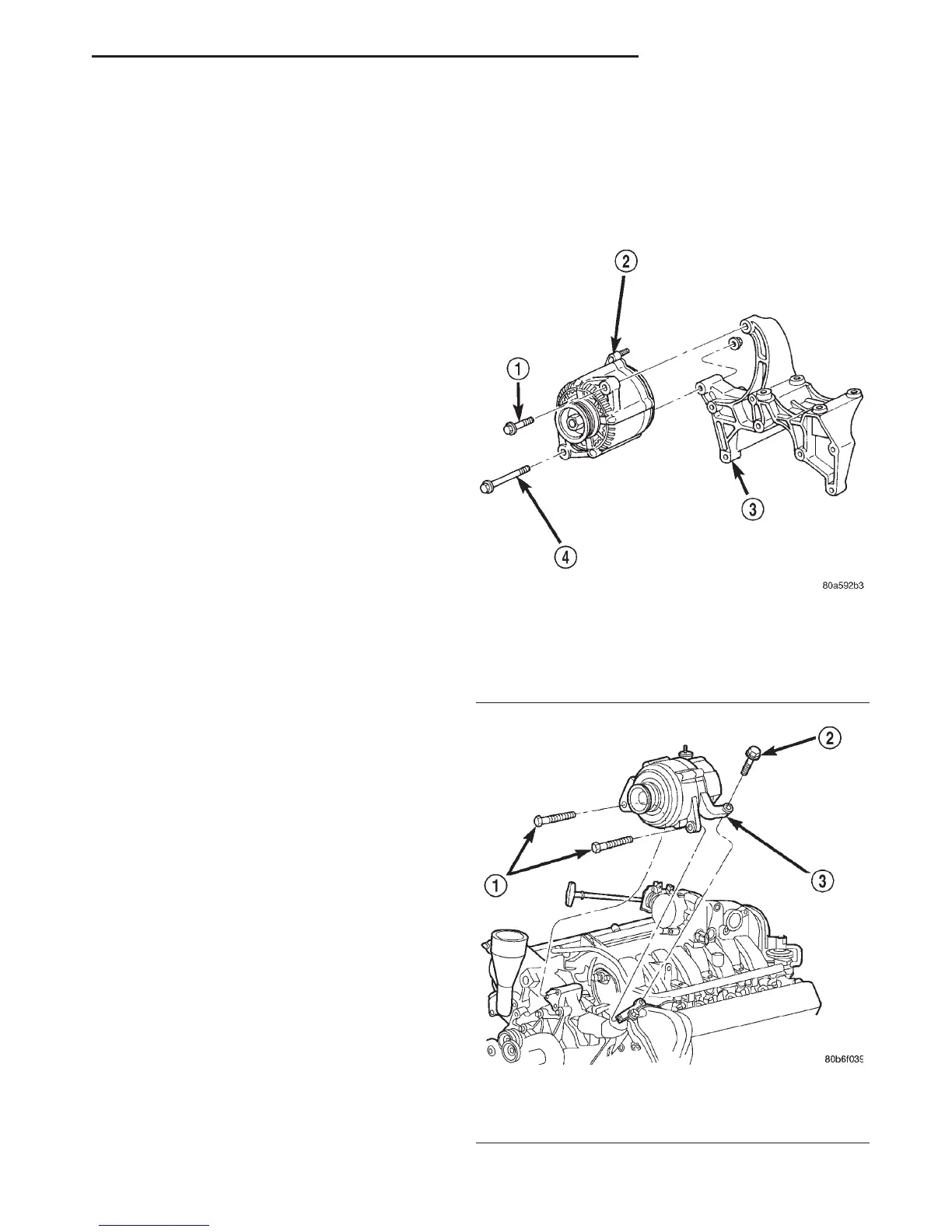
(4) 3.9L/5.2L/5.9L Engines: Remove generator
pivot and mounting bolts/nut (Fig. 1). Position gener-
ator for access to wire connectors.
(5) 4.7L Engine: Remove 3 generator mounting
bolts (Fig. 2). Position generator for access to wire
connectors.
(6) Remove B+ terminal mounting nut at rear of
generator (Fig. 3) or (Fig. 4). Disconnect terminal
from generator.
(7) Disconnect field wire connector at rear of gen-
erator by pushing on connector tab and pulling con-
nector from generator.
(8) Remove generator from vehicle.
Fig. 1 Remove/Install Generator—3.9L/5.2L/5.9L
Engines
1 – MOUNTING BOLT
2 – GENERATOR
3 – MOUNTING BRACKET
4 – MOUNTING BOLT/NUT
Fig. 2 Remove/Install Generator—4.7L V-8 Engine
1 – LOWER BOLTS
2 – REAR BOLT
3 – GENERATOR
DN CHARGING SYSTEM 8C - 3
DIAGNOSIS AND TESTING (Continued)