(2) With key into ignition key cylinder, rotate key
clockwise until retaining pin can be depressed (Fig.
39) or (Fig. 40).
(3) Install key cylinder into ignition switch by
aligning retaining pin into retaining pin slot (Fig.
40). Push key cylinder into switch until retaining pin
engages. After pin engages, rotate key to OFF or
LOCK position.
(4) Check for proper retention of key cylinder by
attempting to pull cylinder from switch.
(5) Automatic Transmission Only: Before attaching
ignition switch to steering column, the transmission
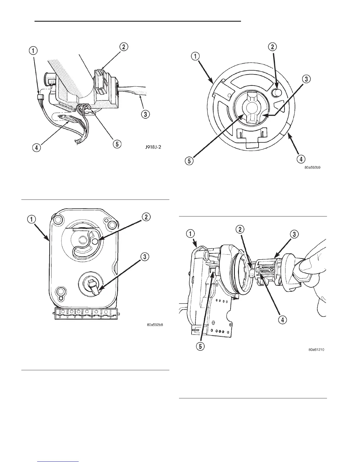
Fig. 37 Ignition Switch and Halo Lamp Connectors
1 – KEY-IN SWITCH & HALO LIGHT
2 – MULTI-FUNCTION SWITCH
3 – TURN SIGNAL SWITCH & LEVER
4 – IGNITION SWITCH
5 – SPEED CONTROL
Fig. 38 Flag in RUN Position
1 – REAR OF IGNITION SWITCH
2 – PARK LOCK DOWEL PIN
(RUN POSITION)
3 – FLAG
(RUN POSITION)
Fig. 39 Key Cylinder—Rear View
1 – IGNITION KEY LOCK CYLINDER
2 – PUSH PIN
3 – RETAINING PIN SLOT
4 – RETAINING PIN
5 – DRIVER
Fig. 40 Installing Key Cylinder Into Switch
1 – IGNITION SWITCH
2 – DRIVER
3 – IGNITION KEY LOCK CYLINDER
4 – RETAINING PIN
5 – RETAINING PIN SLOT
DN IGNITION SYSTEM 8D - 19
REMOVAL AND INSTALLATION (Continued)