NOTE: If a new high-line Central Timer Module is
installed, the programmable features must be
enabled and/or disabled to the customer’s preferred
settings. Use a DRB scan tool and the proper Diag-
nostic Procedures manual to perform these opera-
tions.
INSTRUMENT PANEL ASSEMBLY
WARNING: ON VEHICLES EQUIPPED WITH AIR-
BAGS, REFER TO GROUP 8M - PASSIVE
RESTRAINT SYSTEMS BEFORE ATTEMPTING ANY
STEERING WHEEL, STEERING COLUMN, OR
INSTRUMENT PANEL COMPONENT DIAGNOSIS OR
SERVICE. FAILURE TO TAKE THE PROPER PRE-
CAUTIONS COULD RESULT IN ACCIDENTAL AIR-
BAG DEPLOYMENT AND POSSIBLE PERSONAL
INJURY.
REMOVAL
NOTE: Before starting this procedure, be certain to
turn the steering wheel until the front wheels are in
the straight-ahead position.
(1) Disconnect and isolate the battery negative
cable.
(2) Remove the trim from the right and left front
door sills. Refer to Door Sill Trim Cover in the
Removal and Installation section of Group 23 - Body
for the procedures.
(3) Remove the trim from the left and right cowl
side inner panels. Refer to Cowl Trim Cover in the
Removal and Installation section of Group 23 - Body
for the procedures.
(4) Remove the steering column opening cover
from the instrument panel. Refer to Steering Col-
umn Opening Cover in the Removal and Installa-
tion section of this group for the procedures.
(5) Remove the two screws that secure the inside
hood latch release handle to the instrument panel
lower reinforcement and lower the release handle to
the floor.
(6) Disconnect the driver side airbag module wire
harness connector from the instrument panel wire
harness at the instrument panel lower reinforcement.
(7) If the vehicle is so equipped, disconnect the
overdrive lockout switch wire harness connector from
the instrument panel wire harness near the instru-
ment panel lower reinforcement.
(8) Remove the steering column from the vehicle,
but do not remove the driver side airbag module, the
steering wheel, or the switches from the steering col-
umn. Be certain that the steering wheel is locked
and secured from rotation to prevent the loss of
clockspring centering. Refer to Steering Column in
the Removal and Installation section of Group 19 -
Steering for the procedures.
(9) From under the driver side of the instrument
panel, perform the following:
(a) Remove the screw from the center of the
headlamp and dash to instrument panel bulkhead
wire harness connector and disconnect the connec-
tor.
(b) Disconnect the two body wire harness con-
nectors from the two instrument panel wire har-
ness connectors that are secured to the outboard
side of the instrument panel bulkhead connector.
(c) Disconnect the three wire harness connectors
(one from the body wire harness, and two from the
headlamp and dash wire harness) from the three
junction block connector receptacles located closest
to the dash panel.
(d) Unsnap the plastic retainer clip that secures
the park brake release linkage rod to the lever on
the back side of the park brake release handle and
disengage the linkage rod end from the lever on
the handle.
(e) Disconnect the instrument panel wire har-
ness connector from the stop lamp switch connector
receptacle.
(f) Disconnect the vacuum harness connector
located near the left end of the heater-A/C housing.
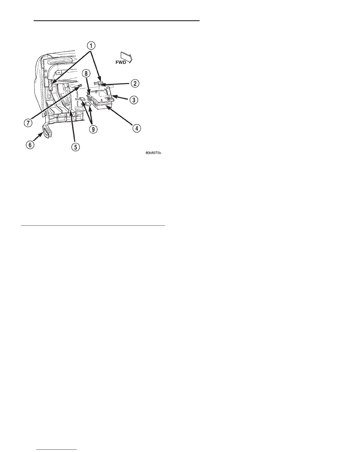
Fig. 23 Central Timer Module Remove/Install
1 – INSTRUMENT PANEL WIRE HARNESS
2 – RETAINER
3 – MOUNTING BRACKET
4 – CENTRAL TIMER MODULE
5 – OUTBOARD GLOVE BOX OPENING BRACKET
6 – END BRACKET
7 – SCREW (2)
8–TAB
9 – WIRE HARNESS CONNECTORS
DN INSTRUMENT PANEL SYSTEMS 8E - 27
REMOVAL AND INSTALLATION (Continued)