(a) If the vehicle is so equipped, reconnect the
two instrument panel wire harness connectors to
the Infinity speaker amplifier connector receptacles
on the right cowl side inner panel.
(b) Install and tighten the nut that secures the
instrument panel wire harness radio ground eyelet
to the stud on the right cowl side inner panel.
Tighten the nut to 3.9 N·m (35 in. lbs.).
(8) Reaching through the instrument panel glove
box opening, perform the following:
(a) Reconnect the two halves of the radio
antenna coaxial cable connector near the center of
the lower instrument panel glove box opening.
(b) Engage the antenna half of the radio
antenna coaxial cable into the retainer clip near
the outboard side of the lower instrument panel
glove box opening.
(c) Reconnect the blower motor wire harness
connector located near the heater-A/C housing sup-
port brace on the inboard side of the instrument
panel glove box opening.
(9) Install the glove box onto the instrument panel.
Refer to Glove Box in the Removal and Installation
section of this group for the procedures.
(10) Install and tighten the screw that secures the
instrument panel wire harness ground eyelets to the
left side of the Airbag Control Module (ACM) mount
on the floor panel transmission tunnel. Tighten the
screw to 3.4 N·m (30 in. lbs.).
(11) Reconnect the instrument panel wire harness
connector to the ACM connector receptacle.
(12) Install the center support bracket onto the
instrument panel. Refer to Instrument Panel Cen-
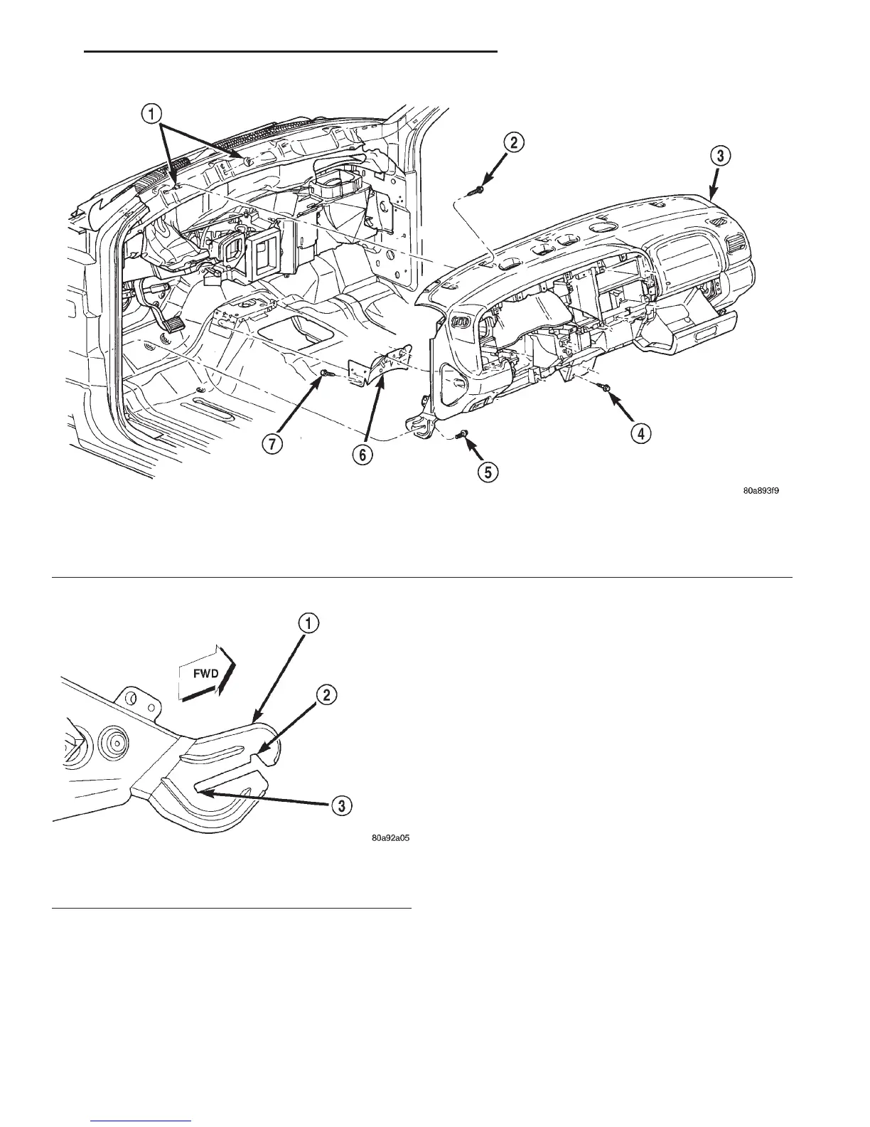
Fig. 24 Instrument Panel Assembly Remove/Install
1 – CLIPS
2 – SCREW
3 – INSTRUMENT PANEL
4 – SCREW
5 – SCREW
6 – CENTER SUPPORT BRACKET
7 – SCREW
Fig. 25 Roll-Down Bracket
1 – ROLL — DOWN BRACKET
2 – ROLL — DOWN SLOT
3 – INSTALLED SLOT
DN INSTRUMENT PANEL SYSTEMS 8E - 29
REMOVAL AND INSTALLATION (Continued)