receiver. The electronic circuitry within the radio is
programmed to respond to these remote radio switch
status messages by adjusting the radio settings as
requested.
For diagnosis of the CTM or the CCD data bus, the
use of a DRB scan tool and the proper Diagnostic
Procedures manual are recommended. For more
information on the features and control functions for
each of the remote radio switches, see the owner’s
manual in the vehicle glove box. For complete circuit
diagrams, refer to Audio System in the Contents of
Group 8W - Wiring Diagrams.
SPEAKER SYSTEM
DESCRIPTION
STANDARD
The standard equipment speaker system includes
speakers in four locations. One full-range 16.5 centi-
meter (6.5 inch) diameter speaker is located in each
front door. There is also one full-range 16.5 centime-
ter (6.5 inch) diameter speaker located in each rear
door.
PREMIUM
The optional premium speaker system features
eight Infinity model speakers in six locations. Each of
the standard speakers in the front doors is replaced
with Infinity model speakers, and an additional 6.9
centimeter (2.75 inch) diameter Infinity dome
tweeter is mounted high in the front door trim pan-
els. The standard speakers in the rear doors are each
replaced with an Infinity 16.5 centimeter (6.5 inch)
diameter coaxial unit. The premium speaker system
also includes an additional Infinity power amplifier.
The total available power of the premium speaker
system is about 100 watts.
OPERATION
STANDARD
Each of the four full-range speakers used in the
standard speaker system is driven by the amplifier
that is integral to the factory-installed radio receiver.
For complete circuit diagrams, refer to Audio Sys-
tem in the Contents of Group 8W - Wiring Diagrams.
PREMIUM
The eight Infinity speakers used in the premium
speaker system are all driven by the radio receiver
through an Infinity power amplifier. For complete cir-
cuit diagrams, refer to Audio System in the Con-
tents of Group 8W - Wiring Diagrams.
POWER AMPLIFIER
DESCRIPTION
Models equipped with the Infinity premium
speaker package have a separate power amplifier
unit. This power amplifier is rated at 100 watts out-
put. The power amplifier unit is mounted to the right
cowl side inner panel under the passenger side end of
the instrument panel. The power amplifier unit can
be accessed for service by removing the trim from the
right cowl side inner panel.
The power amplifier unit should be checked if
there is no sound output noted from the speakers.
For diagnosis of the power amplifier, refer to
Speaker in the Diagnosis and Testing section of this
group. The power amplifier cannot be repaired or
adjusted and, if faulty or damaged, the unit must be
replaced.
OPERATION
The power amplifier receives fused battery current
from a fuse in the Junction Block (JB) at all times.
The internal circuitry of the power amplifier switches
the amplifier on based upon a fused 12 volt output
signal that is received from the radio receiver when-
ever the radio is turned on. The power amplifier
receives the sound signal inputs for four speaker
channels from the radio receiver, then sends the
amplified speaker outputs for each of those channels
to the eight speakers. For complete circuit diagrams,
refer to Audio System in the Contents of Group 8W
- Wiring Diagrams.
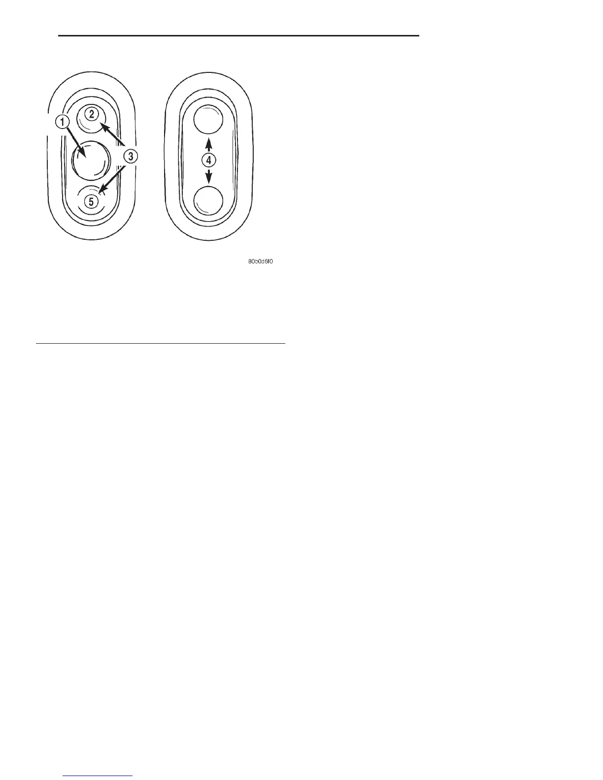
Fig. 1 Remote Radio Switches
1 – PRESET SEEK
2–UP
3 – SEEK
4 – VOLUME
5 – DOWN
DN AUDIO SYSTEMS 8F - 3
DESCRIPTION AND OPERATION (Continued)