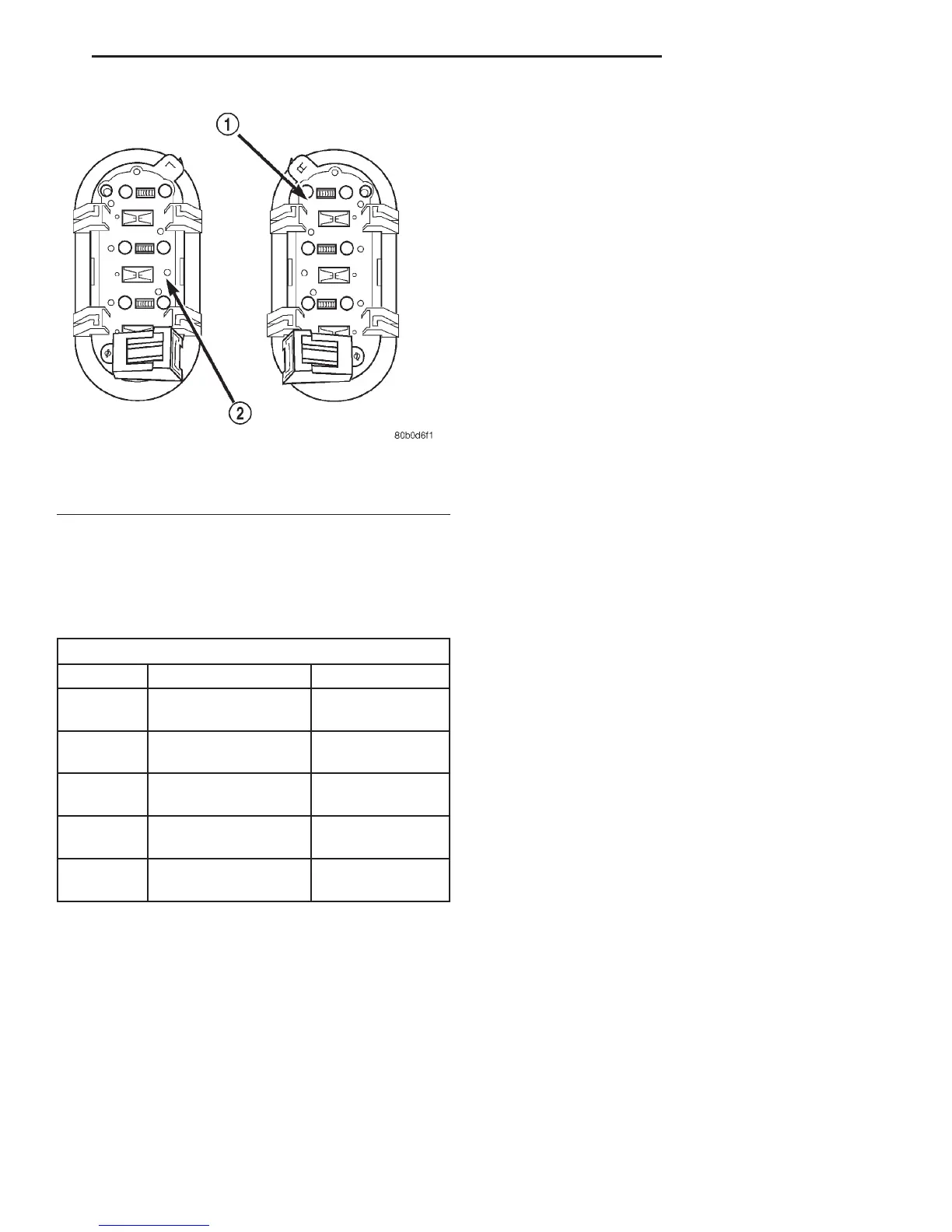
(2) Use an ohmmeter to check the switch resis-
tances as shown in the Remote Radio Switch Test
chart. If the remote radio switch resistances check
OK, go to Step 3. If not OK, replace the faulty
switch.
(3) Check for continuity between the ground cir-
cuit cavity of the remote radio switch wire harness
connector and a good ground. There should be conti-
nuity. If OK, go to Step 4. If not OK, repair the open
ground circuit to ground as required.
(4) Disconnect the 18-way wire harness connector
from the Central Timer Module (CTM). Check for
continuity between the radio control mux circuit cav-
ity of the remote radio switch wire harness connector
and a good ground. There should be no continuity. If
OK, go to Step 5. If not OK, repair the shorted radio
control mux circuit as required.
(5) Check for continuity between the radio control
mux circuit cavities of the remote radio switch wire
harness connector and the 18-way CTM wire harness
connector. There should be continuity. If OK, refer to
the proper Diagnostic Procedures manual to test the
CTM and the Chrysler Collision Detection (CCD)
data bus. If not OK, repair the open radio control
mux circuit as required.
SPEAKER
For complete circuit diagrams, refer to Audio Sys-
tem in the Contents of Group 8W - Wiring Diagrams.
WARNING: ON VEHICLES EQUIPPED WITH AIR-
BAGS, REFER TO GROUP 8M - PASSIVE
RESTRAINT SYSTEMS BEFORE ATTEMPTING ANY
STEERING WHEEL, STEERING COLUMN, OR
INSTRUMENT PANEL COMPONENT DIAGNOSIS OR
SERVICE. FAILURE TO TAKE THE PROPER PRE-
CAUTIONS COULD RESULT IN ACCIDENTAL AIR-
BAG DEPLOYMENT AND POSSIBLE PERSONAL
INJURY.
CAUTION: The speaker output of the radio is a
“floating ground” system. Do not allow any speaker
lead to short to ground, as damage to the radio
may result.
(1) Turn the ignition switch to the On position.
Turn the radio receiver on. Adjust the balance and
fader controls to check the performance of each indi-
vidual speaker. Note the speaker locations that are
not performing correctly. Go to Step 2.
(2) Turn the radio receiver off. Turn the ignition
switch to the Off position. Disconnect and isolate the
battery negative cable. Remove the radio receiver
from the instrument panel. If the vehicle is equipped
with the Infinity speaker package, also disconnect
the wire harness connectors at the power amplifier.
Check both the speaker feed (+) circuit and return (–)
circuit cavities for the inoperative speaker location(s)
at the radio receiver wire harness connectors for con-
tinuity to ground. In each case, there should be no
continuity. If OK, go to Step 3. If not OK, repair the
shorted speaker feed (+) and/or return (–) circuit(s) to
the speaker as required.
(3) If the vehicle is equipped with the Infinity
speaker package, go to Step 6. If the vehicle is
equipped with the standard speaker system, check
the resistance between the speaker feed (+) circuit
and return (–) circuit cavities of the radio receiver
wire harness connectors for the inoperative speaker
location(s). The meter should read between 2 and 28
ohms (speaker resistance). If OK, go to Step 4. If not
OK, go to Step 5.
Fig. 2 Remote Radio Switches
1 – WHITE REAR SWITCH
2 – BLACK REAR SWITCH
REMOTE RADIO SWITCH TEST
SWITCH SWITCH POSITION RESISTANCE
Right
(White)
Volume Up 7320 Ohms
Right
(White)
Volume Down 1210 Ohms
Left
(Black)
Seek Up 4530 Ohms
Left
(Black)
Seek Down 2050 Ohms
Left
(Black)
Pre-Set Station
Advance
10 Ohms
DN AUDIO SYSTEMS 8F - 7
DIAGNOSIS AND TESTING (Continued)