(3) Install speed control cable connector onto throt-
tle body bellcrank pin (snaps on).
(4) Slide accelerator cable plastic mount into
bracket. Continue sliding until tab (Fig. 6) is aligned
to hole in mounting bracket.
(5) Route accelerator cable over top of cable cam
(Fig. 5).
(6) Install accelerator cable connector onto throttle
body bellcrank pin (snaps on).
(7) Install air box housing to throttle body.
(8) Connect negative battery cable at battery.
(9) Before starting engine, operate accelerator
pedal to check for any binding.
VACUUM RESERVOIR
The vacuum reservoir is located under the plastic
cowl plenum cover at lower base of windshield (Fig.
8) or (Fig. 10).
REMOVAL
(1) Disconnect and isolate negative battery at
cable.
(2) Remove both windshield wiper arm/blade
assemblies. Refer to Group 8K, Wiper and Washer
Systems.
(3) Remove rubber weather-strip at front edge of
cowl grill (Fig. 9).
(4) Remove four plastic nuts securing cowl plenum
cover/grille panel to studs on cowl top panel near
base of windshield (Fig. 10).
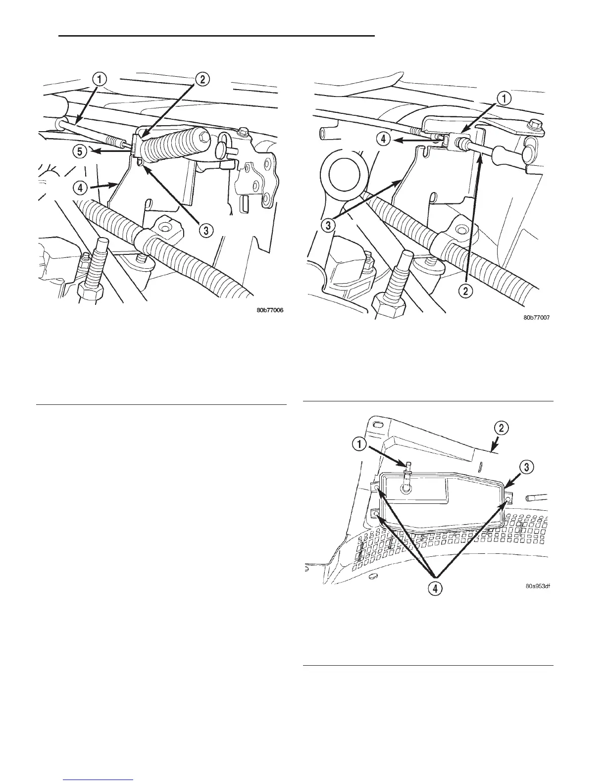
Fig. 6 Accelerator Cable Release Tab—4.7L V-8
Engine
1 – ACCELERATOR CABLE
2 – PLASTIC CABLE MOUNT
3 – PRESS TAB FOR REMOVAL
4 – CABLE BRACKET
5 – SLIDE FOR REMOVAL
Fig. 7 Speed Control Cable at Bracket—4.7L V-8
Engine
1 – PLASTIC CABLE MOUNT
2 – SPEED CONTROL CABLE
3 – BRACKET
4 – SLIDE FOR REMOVAL
Fig. 8 Vacuum Reservoir Mounting
1 – VACUUM SUPPLY CONNECTOR
2 – COWL PLENUM COVER/GRILLE PANEL
3 – VACUUM RESERVOIR
4 – SCREWS
DN SPEED CONTROL SYSTEM 8H - 7
REMOVAL AND INSTALLATION (Continued)