TURN SIGNAL SWITCH AND HAZARD
WARNING SWITCH
WARNING: ON VEHICLES EQUIPPED WITH AIR-
BAGS, REFER TO GROUP 8M - PASSIVE
RESTRAINT SYSTEMS BEFORE ATTEMPTING ANY
STEERING WHEEL, STEERING COLUMN, OR
INSTRUMENT PANEL COMPONENT DIAGNOSIS OR
SERVICE. FAILURE TO TAKE THE PROPER PRE-
CAUTIONS COULD RESULT IN ACCIDENTAL AIR-
BAG DEPLOYMENT AND POSSIBLE PERSONAL
INJURY.
REMOVAL
(1) Disconnect and isolate the battery negative
cable.
(2) If the vehicle is so equipped, unscrew the lever
from the tilt steering column adjuster mechanism
located on the left side of the column just below the
multi-function switch stalk. Turn the lever counter
clockwise to unscrew it from the column.
(3) Remove both the upper and lower shrouds from
the steering column (Fig. 5).
(4) Remove the lower fixed column shroud from
the steering column.
(5) Move the upper fixed column shroud far
enough to access the back of the multi-function
switch (Fig. 6).
(6) Remove the tamper proof mounting screws (a
Snap On tamper proof Torx bit TTXR20B2 or equiv-
alent is required) that secure the multi-function
switch to the steering column.
(7) Gently pull the multi-function switch away
from the steering column far enough to access and
remove the screw that secures the instrument panel
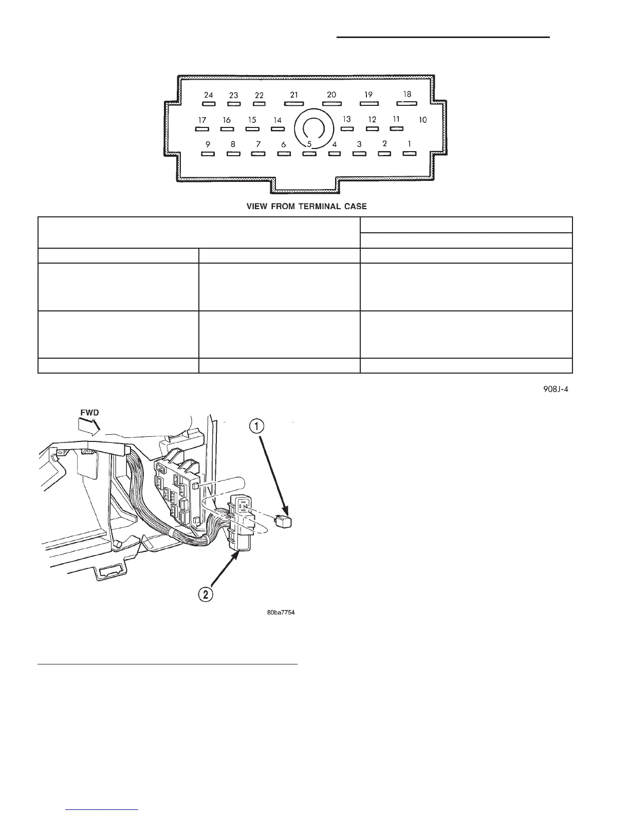
SWITCH POSITIONS
TURN SIGNAL HAZARD WARNING CONTINUITY BETWEEN
NEUTRAL OFF 12 AND 14 AND 15
LEFT OFF 15 AND 16 AND 17
LEFT OFF 12 AND 14
LEFT OFF 22 AND 23 WITH OPTIONAL CORNER LAMPS
RIGHT OFF 11 AND 12 AND 17
RIGHT OFF 14 AND 15
RIGHT OFF 23 AND 24 WITH OPTIONAL CORNER LAMPS
NEUTRAL ON 11 AND 12 AND 13 AND 15 AND 16
Fig. 3 Multi-Function Switch Continuity
Fig. 4 Combination Flasher Remove/Install
1 – ELECTRONIC COMBINATION FLASHER
2 – RELAY AND FUSE BLOCK
8J - 6 TURN SIGNAL AND HAZARD WARNING SYSTEMS DN
REMOVAL AND INSTALLATION (Continued)