WARNING: ON VEHICLES EQUIPPED WITH AIR-
BAGS, REFER TO GROUP 8M - PASSIVE
RESTRAINT SYSTEMS BEFORE ATTEMPTING ANY
STEERING WHEEL, STEERING COLUMN, OR
INSTRUMENT PANEL COMPONENT DIAGNOSIS OR
SERVICE. FAILURE TO TAKE THE PROPER PRE-
CAUTIONS COULD RESULT IN ACCIDENTAL AIR-
BAG DEPLOYMENT AND POSSIBLE PERSONAL
INJURY.
(1) Remove the lower bezel from the instrument
panel and unplug the rear window switch pod wire
harness connector.
(2) Using an ohmmeter, check the rear wiper and
washer switch continuity at the rear window switch
pod terminals as shown in the Rear Wiper Switch
and Washer Switch Continuity chart (Fig. 3).
(3) If the switch fails any of the continuity checks,
replace the faulty rear window switch pod. If the
switch is OK, repair the rear wiper system and/or
washer system wire harness circuits as required.
INTERMITTENT WIPE RELAY
For circuit descriptions and diagrams, refer to
8W-53 - Wipers in Group 8W - Wiring Diagrams.
WARNING: ON VEHICLES EQUIPPED WITH AIR-
BAGS, REFER TO GROUP 8M - PASSIVE
RESTRAINT SYSTEMS BEFORE ATTEMPTING ANY
STEERING WHEEL, STEERING COLUMN, OR
INSTRUMENT PANEL COMPONENT DIAGNOSIS OR
SERVICE. FAILURE TO TAKE THE PROPER PRE-
CAUTIONS COULD RESULT IN ACCIDENTAL AIR-
BAG DEPLOYMENT AND POSSIBLE PERSONAL
INJURY.
RELAY TEST
The intermittent wipe relay (Fig. 4) is located in
the Power Distribution Center (PDC) in the engine
compartment. Refer to the PDC label for intermittent
wipe relay identification and location.
Remove the intermittent wipe relay from the PDC
as described in the Removal and Installation section
of this group to perform the following tests:
(1) A relay in the de-energized position should
have continuity between terminals 87A and 30, and
no continuity between terminals 87 and 30. If OK, go
to Step 2. If not OK, replace the faulty relay.
(2) Resistance between terminals 85 and 86 (elec-
tromagnet) should be 75 6 5 ohms. If OK, go to Step
3. If not OK, replace the faulty relay.
(3) Connect a battery to terminals 85 and 86.
There should now be continuity between terminals
30 and 87, and no continuity between terminals 87A
and 30. If OK, see Relay Circuit Test in the Diagno-
sis and Testing section of this group. If not OK,
replace the faulty relay.
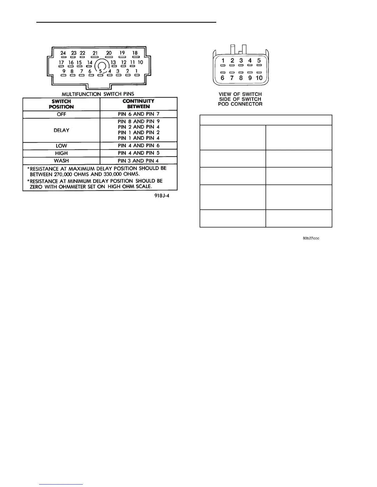
Fig. 2 Multi-Function Switch Continuity
Fig. 3 Rear Wiper Switch and Washer Switch
Continuity
REAR WINDOW SWITCH POD
SWITCH POSITION CONTINUITY
BETWEEN
OFF 3 & 4 (LAMPS)
WIPER SWITCH ON 2 & 7
WASHER SWITCH
ON DEPRESSED
7&8
LAMPS 3 & 4
DN WIPER AND WASHER SYSTEMS 8K - 9
DIAGNOSIS AND TESTING (Continued)