Removal and Installation section of this group for the
procedures.
Use a vacuum cleaner to remove any residual pow-
der from the vehicle interior. Clean from outside the
vehicle and work your way inside, so that you avoid
kneeling or sitting on a non-cleaned area.
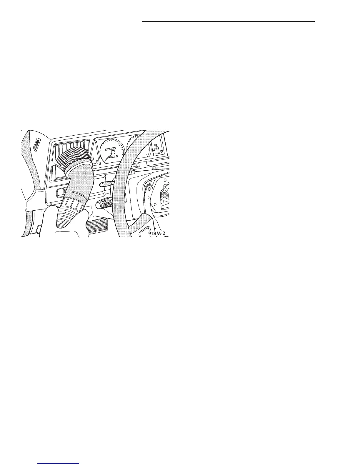
Be sure to vacuum the heater and air conditioning
outlets as well (Fig. 3). Run the heater and air con-
ditioner blower on the lowest speed setting and vac-
uum any powder expelled from the outlets. You may
need to vacuum the interior of the vehicle a second
time to recover all of the powder.
Place the deployed airbag modules in your vehicu-
lar scrap pile.
REMOVAL AND INSTALLATION
DRIVER SIDE AIRBAG MODULE
The following procedure is for replacement of a
faulty or damaged driver side airbag module. If the
driver side airbag has been deployed, the clockspring
and the steering column assembly must also be
replaced. Refer to Clockspring in the Removal and
Installation section of this group for the additional
service procedures for the clockspring. Refer to
Steering Column in the Removal and Installation
section of Group 19 - Steering for the additional ser-
vice procedures for the steering column.
WARNING:
• THE AIRBAG SYSTEM IS A SENSITIVE, COM-
PLEX ELECTROMECHANICAL UNIT. BEFORE
ATTEMPTING TO DIAGNOSE OR SERVICE ANY AIR-
BAG SYSTEM OR RELATED STEERING WHEEL,
STEERING COLUMN, OR INSTRUMENT PANEL
COMPONENTS YOU MUST FIRST DISCONNECT
AND ISOLATE THE BATTERY NEGATIVE (GROUND)
CABLE. THEN WAIT TWO MINUTES FOR THE SYS-
TEM CAPACITOR TO DISCHARGE BEFORE FUR-
THER SYSTEM SERVICE. THIS IS THE ONLY SURE
WAY TO DISABLE THE AIRBAG SYSTEM. FAILURE
TO DO THIS COULD RESULT IN ACCIDENTAL AIR-
BAG DEPLOYMENT AND POSSIBLE PERSONAL
INJURY.
• WHEN REMOVING A DEPLOYED AIRBAG MOD-
ULE, RUBBER GLOVES, EYE PROTECTION, AND A
LONG-SLEEVED SHIRT SHOULD BE WORN. THERE
MAY BE DEPOSITS ON THE AIRBAG MODULE AND
OTHER INTERIOR SURFACES. IN LARGE DOSES,
THESE DEPOSITS MAY CAUSE IRRITATION TO THE
SKIN AND EYES.
REMOVAL
(1) Disconnect and isolate the battery negative
cable. If either of the airbags has not been deployed,
wait two minutes for the system capacitor to dis-
charge before further service.
(2) From the underside of the steering wheel,
remove the two screws that secure the driver side
airbag module to the steering wheel (Fig. 4).
(3) Pull the airbag module away from the steering
wheel far enough to access the two wire harness con-
nectors on the back of the airbag module.
(4) Disconnect the clockspring horn switch wire
harness connector from the horn switch feed wire
connector, which is located on the back of the airbag
module.
(5) The clockspring airbag wire harness connector
is a tight snap-fit into the airbag module connector
receptacle, which is located on the airbag inflator on
the back of the airbag module. Firmly grasp and pull
or gently pry on the clockspring airbag wire harness
connector to disconnect it from the airbag module.
Do not pull on the clockspring wire harness to
disengage the connector from the airbag mod-
ule connector receptacle.
(6) Remove the driver side airbag module from the
steering wheel.
(7) If the driver side airbag has been deployed, the
clockspring and the steering column must be
replaced. Refer to Clockspring in the Removal and
Installation section of this group for the clockspring
service procedures. Refer to Steering Column in the
Removal and Installation section of Group 19 - Steer-
ing for the additional service procedures for the
steering column.
Fig. 3 Vacuum Heater and A/C Outlets - Typical
8M - 6 PASSIVE RESTRAINT SYSTEMS DN
SERVICE PROCEDURES (Continued)











 To Next Page