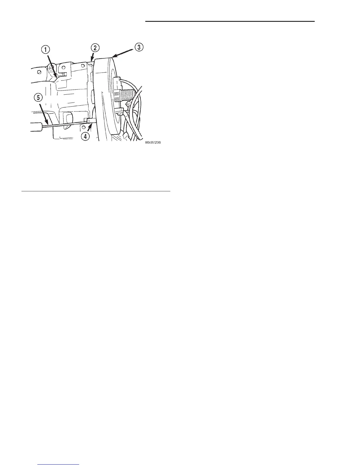
(14) Using a small screwdriver, gently pry under
the plastic latches at the side and the top of the
clockspring assembly to disengage them from the
receptacles in the steering column lock housing and
remove the clockspring from the column. The clock-
spring cannot be repaired. It must be replaced if
faulty or damaged, or if the driver side airbag has
been deployed.
INSTALLATION
If the clockspring is not properly centered in rela-
tion to the steering wheel, steering shaft and steer-
ing gear, it may be damaged. Refer to Clockspring
Centering in the Adjustments section of this group
before installing or reinstalling a clockspring.
Service replacement clocksprings are shipped pre-
centered and with a piece of tape covering the
depressed clockspring auto-locking tabs. This tape
should not be removed until the clockspring has been
installed on the steering column. If the tape is
removed before the clockspring is installed on a
steering column, the clockspring centering procedure
must be performed.
NOTE: Before starting this procedure, be certain
that the front wheels are still in the straight-ahead
position.
(1) Carefully slide the centered clockspring down
over the steering column upper shaft until the plastic
latches at the side and the top of the clockspring
assembly latches engage the receptacles in the steer-
ing column lock housing.
(2) Reconnect the lower clockspring wire harness
connector to the instrument panel wire harness. Be
certain that the wire harness locator clips are prop-
erly seated on the outside of the wiring trough and
that the connector latches are fully engaged.
(3) Reconnect the instrument panel wire harness
connector to the lower clockspring connector recepta-
cle.
(4) Position the multi-function switch onto the left
side of the steering column lock housing.
(5) Install and tighten the two screws that secure
the multi-function switch to the left side of the steer-
ing column lock housing. Tighten the screws to 2
N·m (17 in. lbs.).
(6) Install the steering column shrouds. Be certain
that the lower clockspring wire harness is routed
inside the shrouds.
(7) Install the steering column opening cover onto
the instrument panel. Refer to Steering Column
Opening Cover in the Removal and Installation sec-
tion of Group 8E - Instrument Panel Systems for the
procedures.
(8) Install the steering wheel onto the steering col-
umn upper shaft. Be certain to index the flats on the
hub of the steering wheel with the formations on the
inside of the clockspring hub. Pull the upper clock-
spring wire harnesses through the upper and lower
holes between the steering wheel back trim cover and
the steering wheel armature.
(9) Install and tighten the steering wheel mount-
ing nut. Tighten the nut to 61 N·m (45 ft. lbs.). Be
certain not to pinch the wire harnesses between the
steering wheel and the nut.
(10) If the vehicle is so equipped, reconnect the
upper clockspring wire harness connectors to the
vehicle speed control switches and/or the remote
radio switches. Be certain that the upper clockspring
wire harnesses are routed between the steering
wheel back trim cover and the steering wheel arma-
ture.
(11) If the vehicle is so equipped, install the tilt
steering column lever onto the left side of the steer-
ing column by screwing it into place.
(12) Install the driver side airbag module onto the
steering wheel. Refer to Driver Side Airbag Mod-
ule in the Removal and Installation section of this
group for the procedures.
ADJUSTMENTS
CLOCKSPRING CENTERING
The clockspring is designed to wind and unwind
when the steering wheel is rotated, but is only
designed to rotate the same number of turns (about
five complete rotations) as the steering wheel can be
turned from stop to stop. Centering the clockspring
Fig. 14 Clockspring Latches
1 – STEERING COLUMN LOCK HOUSING
2 – TOP LATCH
3 – CLOCKSPRING
4 – SIDE LATCH
5 – SCREWDRIVER
8M - 14 PASSIVE RESTRAINT SYSTEMS DN
REMOVAL AND INSTALLATION (Continued)















 To Next Page