not OK, repair the circuit to the junction block fuse
as required.
(5) Turn the ignition switch to the Off position.
Disconnect and isolate the battery negative cable.
Plug the wire harness connector into the rear win-
dow switch pod. Connect the battery negative cable.
Turn the ignition switch to the On position. Back
probe the rear window defogger relay output circuit
cavity of the rear window switch pod wire harness
connector. Depress and release the rear window
defogger switch. There should be battery voltage.
Depress and release the rear window defogger switch
again. There should be zero volts. If OK, go to Step 6.
If not OK, replace the faulty rear window switch pod.
(6) Depress and release the rear window defogger
switch. The rear window defogger indicator lamp
should light. If the indicator lamp does not light,
replace the bulb with a known good unit and test
again. If the lamp is still inoperative, replace the
faulty rear window switch pod.
SERVICE PROCEDURES
REAR GLASS HEATING GRID REPAIR
Repair of the rear glass heating grid lines, bus
bars, terminals or pigtail wires can be accomplished
using a Mopar Rear Window Defogger Repair Kit
(Part Number 4267922) or equivalent.
WARNING: MATERIALS CONTAINED IN THE
REPAIR KIT MAY CAUSE SKIN OR EYE IRRITATION.
THE KIT CONTAINS EPOXY RESIN AND AMINE
TYPE HARDENER, WHICH ARE HARMFUL IF SWAL-
LOWED. AVOID CONTACT WITH THE SKIN AND
EYES. FOR SKIN CONTACT, WASH THE AFFECTED
AREAS WITH SOAP AND WATER. FOR CONTACT
WITH THE EYES, FLUSH WITH PLENTY OF WATER.
DO NOT TAKE INTERNALLY. IF TAKEN INTER-
NALLY, INDUCE VOMITING AND CALL A PHYSICIAN
IMMEDIATELY. USE WITH ADEQUATE VENTILA-
TION. DO NOT USE NEAR FIRE OR FLAME. CON-
TAINS FLAMMABLE SOLVENTS. KEEP OUT OF THE
REACH OF CHILDREN.
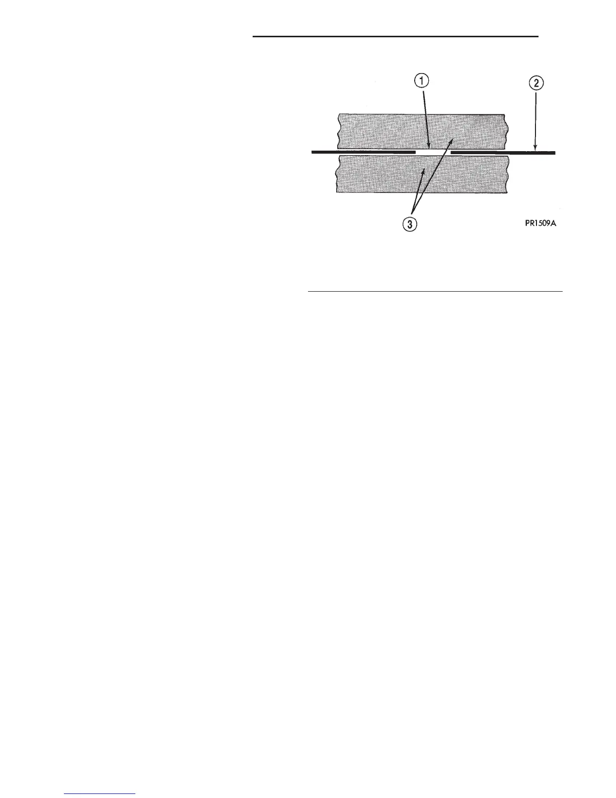
(1) Mask the repair area so that the conductive
epoxy can be applied neatly. Extend the epoxy appli-
cation onto the grid line or the bus bar on each side
of the break (Fig. 2).
(2) Follow the instructions in the repair kit for
preparing the damaged area.
(3) Remove the package separator clamp and mix
the two conductive epoxy components thoroughly
within the packaging. Fold the package in half and
cut the center corner to dispense the epoxy.
(4) For grid line repairs, mask the area to be
repaired with masking tape or a template.
(5) Apply the epoxy through the slit in the mask-
ing tape or template. Overlap both ends of the break
by at least 19 millimeters (0.75 inch).
(6) For a terminal or pigtail wire replacement,
mask the adjacent areas so the epoxy can be
extended onto the adjacent grid line as well as the
bus bar. Apply a thin layer of epoxy to the area
where the terminal or pigtail wire was fastened and
onto the adjacent grid line.
(7) Apply a thin layer of conductive epoxy to the
terminal or bare wire end of the pigtail and place it
in the proper location on the bus bar. To prevent the
terminal or pigtail wire from moving while the epoxy
is curing, it must be wedged or clamped.
(8) Carefully remove the masking tape or tem-
plate.
CAUTION: Do not allow the glass surface to exceed
204° C (400° F) or the glass may fracture.
(9) Allow the epoxy to cure 24 hours at room tem-
perature, or use a heat gun with a 260° to 371° C
(500° to 700° F) range for fifteen minutes. Hold the
heat gun approximately 25.4 centimeters (10 inches)
from the repair.
(10) After the conductive epoxy is properly cured,
remove the wedge or clamp from the terminal or pig-
tail wire. Do not attach the wire harness connectors
until the curing process is complete.
(11) Check the operation of the rear window defog-
ger glass heating grid.
Fig. 2 Grid Line Repair - Typical
1 – BREAK
2 – GRID LINE
3 – MASKING TAPE
8N - 4 ELECTRICALLY HEATED SYSTEMS DN
DIAGNOSIS AND TESTING (Continued)







 To Next Page