Remove the relay (Fig. 3) from the PDC, JB or the
relay and fuse block as described in this group to
perform the following tests:
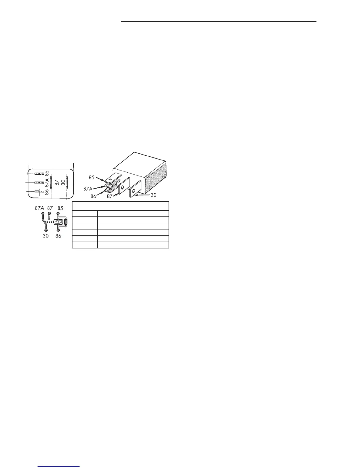
(1) A relay in the de-energized position should
have continuity between terminals 87A and 30, and
no continuity between terminals 87 and 30. If OK, go
to Step 2. If not OK, replace the faulty relay.
(2) Resistance between terminals 85 and 86 (elec-
tromagnet) should be 75 6 5 ohms. If OK, go to Step
3. If not OK, replace the faulty relay.
(3) Connect a battery to terminals 85 and 86.
There should now be continuity between terminals
30 and 87, and no continuity between terminals 87A
and 30. If OK, test the relay circuits. If not OK,
replace the faulty relay.
SERVICE PROCEDURES
REMOTE KEYLESS ENTRY TRANSMITTER
BATTERY REPLACEMENT
The Remote Keyless Entry (RKE) transmitter case
snaps open and shut for battery access. To replace
the RKE transmitter batteries:
(1) Using a trim stick or another suitable wide
flat-bladed tool, gently pry at the center seam of the
transmitter case halves near the key ring until the
two halves unsnap.
(2) Lift the back half of the transmitter case off of
the transmitter.
(3) Remove the two batteries from the transmitter.
(4) Replace the two batteries with new Duracell
DL2016, or their equivalent. Be certain that the bat-
teries are installed with their polarity correctly ori-
ented.
(5) Align the two transmitter case halves with
each other, and squeeze them firmly together until
they snap back into place.
REMOTE KEYLESS ENTRY TRANSMITTER
PROGRAMMING
To program the Remote Keyless Entry (RKE)
transmitter access codes into the RKE receiver in the
Central Timer Module (CTM) requires the use of a
DRB scan tool. Refer to the proper Diagnostic Proce-
dures manual for more information.
REMOVAL AND INSTALLATION
POWER LOCK SWITCH
DRIVER SIDE FRONT DOOR
(1) Disconnect and isolate the battery negative
cable.
(2) Remove the trim panel from the inside of the
driver side front door. Refer to Group 23 - Body for
the procedures.
(3) From the back side of the trim panel, remove
the screws that secure the power window and lock
switch unit to the switch bezel in the door trim panel
opening.
(4) Remove the power window and lock switch and
the switch bezel from the door trim panel.
(5) Reverse the removal procedures to install.
Tighten the mounting screws to 2.2 N·m (20 in. lbs.).
PASSENGER SIDE FRONT DOOR
(1) Disconnect and isolate the battery negative
cable.
(2) Remove the trim panel from the inside of the
passenger side front door. Refer to Group 23 - Body
for the procedures.
(3) With a small thin-bladed screwdriver, gently
pry the snap clips at the sides of the power lock
switch receptacle on the back of the door trim panel
switch bezel and pull the switch out of the receptacle.
(4) Reverse the removal procedures to install. Be
certain that both of the switch snap retainers in the
receptacle on the back of the door trim panel switch
bezel are fully engaged.
POWER LOCK MOTOR
DOOR
The power lock motor is integral to the door latch
unit. If the power lock motor is faulty or damaged,
the entire door latch unit must be replaced. Refer to
Group 23 - Body for the door latch service proce-
dures.
LIFTGATE
(1) Disconnect and isolate the battery negative
cable.
TERMINAL LEGEND
NUMBER IDENTIFICATION
30 COMMON FEED
85 COIL GROUND
86 COIL BATTERY
87 NORMALLY OPEN
87A NORMALLY CLOSED
Fig. 3 Relay Terminals
8P - 8 POWER LOCK SYSTEMS DN
DIAGNOSIS AND TESTING (Continued)