(2) Using an ohmmeter, perform the switch resis-
tance checks between the two cavities of the liftgate
lock cylinder switch wire harness connector. Actuate
the switch by rotating the key in the liftgate lock cyl-
inder to test for the proper resistance values in each
of the three switch positions, as shown in the Lift-
gate Lock Cylinder Switch chart.
(3) If a liftgate lock cylinder switch fails any of the
resistance tests, replace the faulty switch as
required.
RELAYS
The headlamp (or security) and horn relays are
located in the Power Distribution Center (PDC) in
the engine compartment. Each of these relays can be
tested as described in the following procedure, how-
ever the circuits they are used in do vary. To test the
relay circuits, refer to the circuit descriptions and
diagrams in 8W-39 - Vehicle Theft Security System
in Group 8W - Wiring Diagrams.
WARNING: ON VEHICLES EQUIPPED WITH AIR-
BAGS, REFER TO GROUP 8M - PASSIVE
RESTRAINT SYSTEMS BEFORE ATTEMPTING ANY
STEERING WHEEL, STEERING COLUMN, OR
INSTRUMENT PANEL COMPONENT DIAGNOSIS OR
SERVICE. FAILURE TO TAKE THE PROPER PRE-
CAUTIONS COULD RESULT IN ACCIDENTAL AIR-
BAG DEPLOYMENT AND POSSIBLE PERSONAL
INJURY.
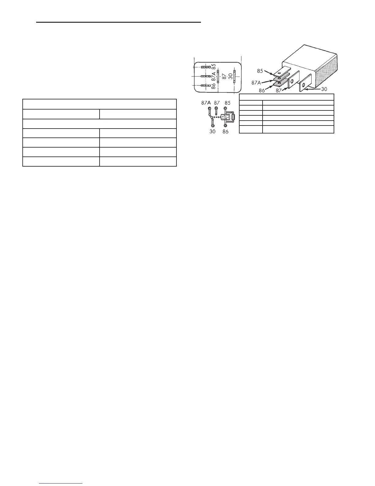
Remove the relay (Fig. 1) from the PDC as
described in this group to perform the following tests:
(1) A relay in the de-energized position should
have continuity between terminals 87A and 30, and
no continuity between terminals 87 and 30. If OK, go
to Step 2. If not OK, replace the faulty relay.
(2) Resistance between terminals 85 and 86 (elec-
tromagnet) should be 75 6 5 ohms. If OK, go to Step
3. If not OK, replace the faulty relay.
(3) Connect a battery to terminals 85 and 86.
There should now be continuity between terminals
30 and 87, and no continuity between terminals 87A
and 30. If OK, test the relay circuits. If not OK,
replace the faulty relay.
REMOVAL AND INSTALLATION
DOOR AJAR SWITCH
The door ajar switch is integral to the door latch
unit. If the door ajar switch is faulty or damaged, the
entire door latch unit must be replaced. Refer to
Group 23 - Body for the door latch service proce-
dures.
LIFTGATE AJAR SWITCH
The liftgate ajar switch is integral to the liftgate
latch unit. If the liftgate ajar switch is faulty or dam-
aged, the entire liftgate latch unit must be replaced.
Refer to Group 23 - Body for the liftgate latch service
procedures.
DOOR LOCK CYLINDER SWITCH
(1) Disconnect and isolate the battery negative
cable.
(2) Remove the door outside latch handle mount-
ing hardware and linkage from the inside of the door.
Refer to Group 23 - Body for the procedures.
(3) From the outside of the door, pull the door out-
side latch handle out far enough to access the door
lock cylinder switch (Fig. 2).
(4) Disengage the door lock cylinder switch from
the back of the lock cylinder.
(5) Unplug the door lock cylinder switch wire har-
ness connector.
(6) Disengage the retainers that secure the door
lock cylinder switch wire harness to the inner door
panel.
(7) Remove the door lock cylinder switch from the
door.
(8) Reverse the removal procedures to install.
LIFTGATE LOCK CYLINDER SWITCH
(1) Disconnect and isolate the battery negative
cable.
(2) Remove the trim panel from the liftgate inner
panel. Refer to Group 23 - Body for the procedures.
LIFTGATE LOCK CYLINDER SWITCH
Switch Position Resistance
Neutral 12 Kilohms
Lock (Counter Clockwise) 644 Ohms
Unlock (Clockwise) 1565 Ohms
TERMINAL LEGEND
NUMBER IDENTIFICATION
30 COMMON FEED
85 COIL GROUND
86 COIL BATTERY
87 NORMALLY OPEN
87A NORMALLY CLOSED
Fig. 1 Relay Terminals
DN VEHICLE THEFT/SECURITY SYSTEMS 8Q - 5
DIAGNOSIS AND TESTING (Continued)