Motor in the Diagnosis and Testing section of this
group. If not OK, repair the open circuit(s) as
required.
NOTE: All passenger door power window switches
receive their battery and ground feed for operating
the passenger door power window motors through
the driver side power window and lock master
switch and wire harness connector.
CIRCUIT BREAKER
For circuit descriptions and diagrams, refer to 8W-60
- Power Windows in Group 8W - Wiring Diagrams.
(1) Locate the circuit breaker in the junction block.
Pull out the circuit breaker slightly, but be certain
that the circuit breaker terminals still contact the
terminals in the junction block cavities.
(2) Connect the negative lead of a 12-volt DC volt-
meter to a good ground.
(3) With the voltmeter positive lead, check both
terminals of the circuit breaker for battery voltage.
If only one terminal has battery voltage, the circuit
breaker is faulty and must be replaced. If neither ter-
minal has battery voltage, repair the open circuit
from the Power Distribution Center (PDC) as
required. If the circuit breaker checks OK, but no
power windows operate, see Power Window System
in the Diagnosis and Testing section of this group.
POWER WINDOW SWITCH
The Light-Emitting Diode (LED) illumination
lamps for all of the power window and lock switch
and bezel unit switch paddles receive battery current
through the power window circuit breaker in the
junction block. If all of the LEDs are inoperative in
both the power window and lock switch units and the
power windows are inoperative, perform the diagno-
sis for Power Window System in this group. If the
power windows operate, but any or all of the LEDs
are inoperative, the power window and lock switch
units with the inoperative LED(s) is faulty and must
be replaced. For circuit descriptions and diagrams,
refer to 8W-60 - Power Windows in Group 8W - Wir-
ing Diagrams.
(1) Check the circuit breaker in the junction block.
If OK, go to Step 2. If not OK, replace the faulty cir-
cuit breaker.
(2) Turn the ignition switch to the On position.
Check for battery voltage at the circuit breaker in
the junction block. If OK, turn the ignition switch to
the Off position and go to Step 3. If not OK, repair
the circuit to the ignition switch as required.
(3) Disconnect and isolate the battery negative
cable. Remove the power window switch unit from
the door trim panel. Unplug the wire harness connec-
tor from the switch unit.
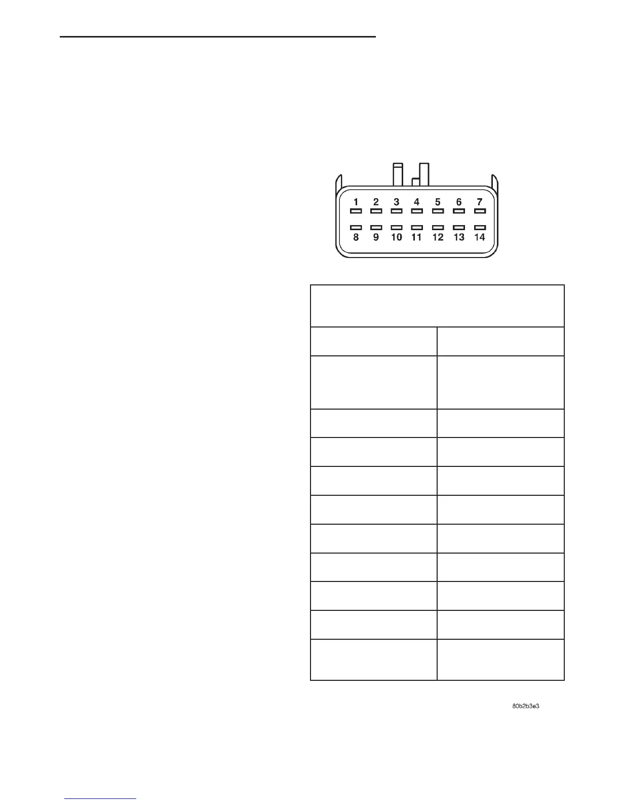
(4) Test the power window switch continuity. See
the Power Window Switch Continuity charts to deter-
mine if the continuity is correct in the Off, Up and
Down switch positions (Fig. 1) or (Fig. 2). If OK, see
Power Window Motor in the Diagnosis and Testing
section of this group. If not OK, replace the faulty
switch.
Fig. 1 Power Window Switch Continuity - Driver
Side Front
DRIVER SIDE FRONT WINDOW SWITCH
(MASTER)
SWITCH POSITION CONTINUITY BETWEEN
OFF 2&5,3&5,5&6,
5&11,5&12,5&13,
5&14
RIGHT REAR UP 4 & 12,5&11
RIGHT REAR DOWN 4 & 11,5&12
RIGHT FRONT UP 2 & 5,3&4
RIGHT FRONT DOWN 2 & 4,3&5
LEFT REAR UP 4 & 14,5&13
LEFT REAR DOWN 4 & 13,5&14
LEFT FRONT UP 4 & 6, SEE NOTE
LEFT FRONT DOWN 5 & 6, SEE NOTE
POWER WINDOW
LOCKOUT OFF
4&7
DN POWER WINDOW SYSTEMS 8S - 3
DIAGNOSIS AND TESTING (Continued)