cuits between the power mirror and the power mirror
switch for a short or open as required.
REMOVAL AND INSTALLATION
POWER MIRROR SWITCH
(1) Disconnect and isolate the battery negative
cable.
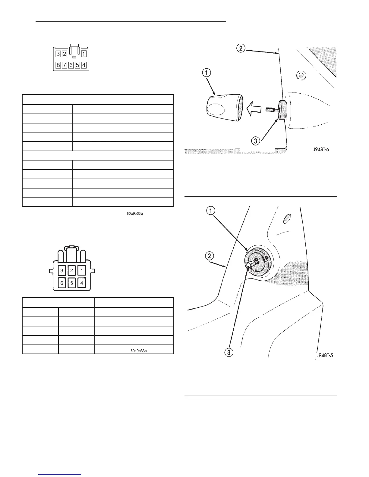
(2) Pull the power mirror switch control knob rear-
ward to remove it from the switch stem (Fig. 4).
(3) Remove the nut that secures the power mirror
switch to the driver side door trim panel (Fig. 5).
(4) Remove the trim panel from the inside of the
driver side front door. Refer to Group 23 - Body for
the procedures.
(5) Pull the trim panel away from the inner door
panel far enough to access the power mirror switch
wire harness connector.
MIRROR SELECTOR KNOB IN “L” POSITION
MOVE LEVER CONTINUITY BETWEEN
UP Pins 3 and 8, 1 and 7, 4 and 7
RIGHT Pins 3 and 7, 2 and 8, 5 and 8
DOWN Pins 3 and 7, 1 and 8, 4 and 8
LEFT Pins 3 and 8, 2 and 7, 5 and 7
MIRROR SELECTOR KNOB IN “R” POSITION
MOVE LEVER CONTINUITY BETWEEN
UP Pins 6 and 8, 1 and 7, 4 and 7
RIGHT Pins 6 and 7, 2 and 8, 4 and 8
DOWN Pins 6 and 7, 1 and 8, 4 and 8
LEFT Pins 6 and 8, 2 and 7, 5 and 7
Fig. 2 Power Mirror Switch Continuity
Left or Right Mirror
12 Volts Ground MIRROR MOVEMENT
Pin 3 Pin 1 UP
Pin 1 Pin 3 DOWN
Pin 2 Pin 1 LEFT
Pin 1 Pin 2 RIGHT
Fig. 3 Power Mirror Test
Fig. 4 Power Mirror Switch Control Knob Remove/
Install - Typical
1 – SWITCH CONTROL KNOB
2 – DOOR TRIM PANEL
3 – POWER MIRROR SWITCH
Fig. 5 Power Mirror Switch Nut - Typical
1 – SWITCH RETAINING NUT
2 – DOOR TRIM PANEL
3 – POWER MIRROR SWITCH
DN POWER MIRROR SYSTEMS 8T - 3
DIAGNOSIS AND TESTING (Continued)