PISTON RINGS—FITTING
RING END GAP
Before reinstalling used rings or installing new
rings, the ring clearances must be checked.
(1) Wipe the cylinder bore clean.
(2) Insert the ring in the cylinder bore.
NOTE: The ring gap measurement must be made
with the ring positioned at least 12mm (0.50 inch.)
from bottom of cylinder bore.
(3) Using a piston, to ensure that the ring is
squared in the cylinder bore, slide the ring downward
into the cylinder.
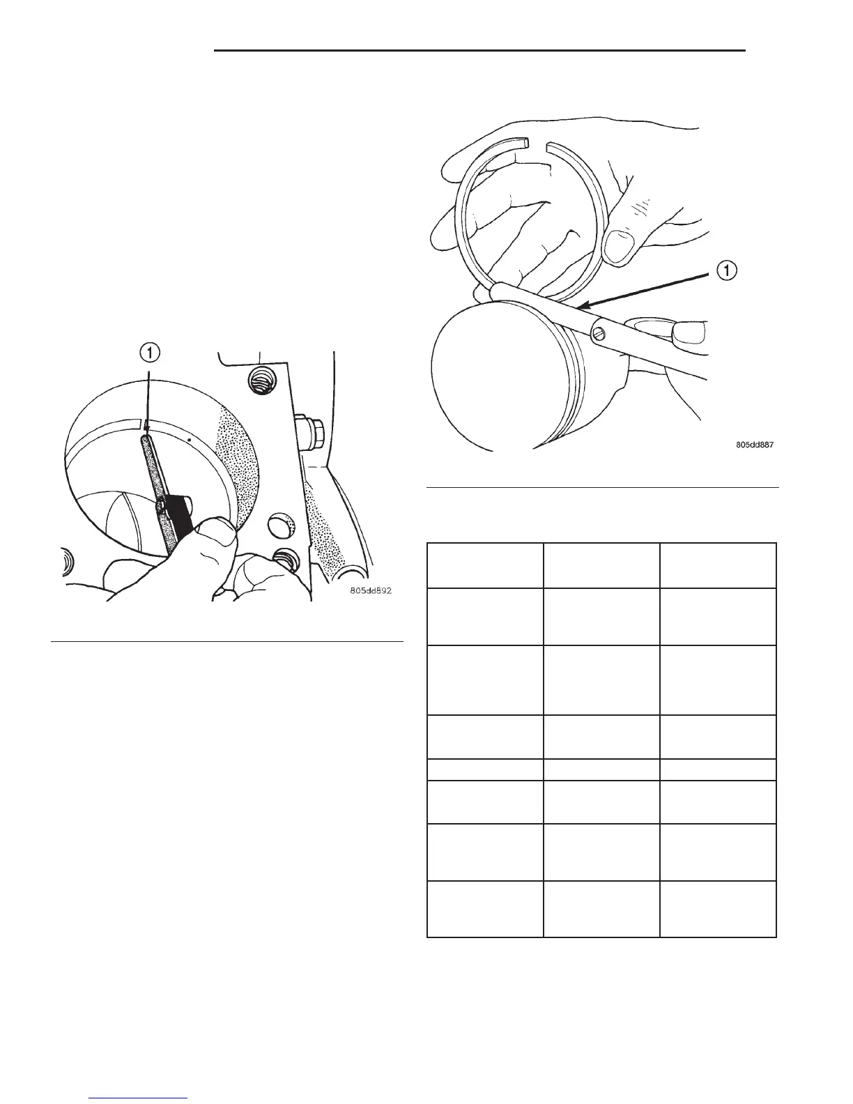
(4) Using a feeler gauge check the ring end gap
(Fig. 20). Replace any rings not within specification.
PISTON RING SIDE CLEARANCE
NOTE: Make sure the piston ring grooves are clean
and free of nicks and burrs.
(5) Measure the ring side clearance as shown (Fig.
21) make sure the feeler gauge fits snugly between
the ring land and the ring. Replace any ring not
within specification.
(6) Rotate the ring around the piston, the ring
must rotate in the groove with out binding.
EARLY BUILD
(7) The No. 1 and No. 2 piston rings have a differ-
ent cross section. Ensure No. 2 ring is installed with
manufacturers I.D. mark (Dot) facing up, towards top
of the piston.
LATE BUILD
The No. 1 and No. 2 piston rings have a different
cross section. Ensure No. 2 ring is installed with
manufacturers I.D. mark (Dot) facing up, towards top
of the piston. On late build engines the piston top
ring groove and crown are not anodized therefore,
the No. 1 piston ring is coated with an anti-friction
coating. Care must be used to ensure that when
installing piston rings on late build engines that the
correct No. 1 piston ring be installed, failure to use
the correct piston ring can cause severe damage to
the piston and/or cylinder block.
Fig. 20 Ring End Gap Measurement—Typical
1 – FEELER GAUGE
Fig. 21 Measuring Piston Ring Side Clearance
1 – FEELER GAUGE
PISTON RING SPECIFICATION CHART
Ring Position Groove Maximum
Clearance Clearance
Upper Ring .051-.094mm 0.11mm
(0.0020-.0037
in.)
(0.004 in.)
Intermediate
Ring
0.04-0.08mm 0.10mm
(0.0016-0.0031
in.)
(0.004 in.)
Oil Control Ring .019-.229mm .25mm
(Steel Rails) (.0007-.0090 in.) (0.010 in.)
Ring Position Ring Gap Wear Limit
Upper Ring 0.20-0.36mm 0.40mm
(0.008-0.014 in.) (0.0016in.)
Intermediate
Ring
0.37-0.63mm 0.71mm
(0.014-0.025 in.) (0.028in.)
Oil Control Ring 0.025-0.76mm 1.52mm
(Steel Rail) (0.010- 0.030
in.)
(0.060in.)
9 - 24 4.7L ENGINE DN
SERVICE PROCEDURES (Continued)
2000 DN Service Manual
Publication No. 81-370-0016
TSB 26-12-99 December, 1999