(2) 4X4 vehicles Install locknuts onto the engine
mount brackets. Tighten locknuts to 41 N·m (30 ft.
lbs.).
(3) Remove jack from under the transmission.
(4) Remove Engine Lifting Fixture Special Tool
8347 (Fig. 47).
(5) Remove Special Tools 8400 Lifting Studs.
(6) Position generator wiring behind the oil dip-
stick tube, then install the oil dipstick tube upper
mounting bolt.
(7) Connect both left and right side body ground
straps.
(8) Install power steering pump.
(9) Connect fuel supply line quick connect fitting.
(10) Connect the vacuum lines at the throttle body
and intake manifold.
(11) Connect engine harness at the following
points (Fig. 46) :
• Intake Air Temperature (IAT) Sensor
• Idle Air Control (IAC) Motor
• Fuel Injectors
• Throttle Position (TPS) Switch
• Engine Oil Pressure Switch
• Engine Coolant Temperature (ECT) Sensor
• Manifold Absolute Pressure (MAP) Sensor
• Camshaft Position (CMP) Sensor
• Coil Over Plugs
(12) Position and install heater hoses and tubes
onto intake manifold.
(13) Install the heater hoses onto the heater core
and the engine front cover.
(14) Install generator.
(15) Install A/C condenser, radiator and transmis-
sion oil cooler as an assembly.
(16) Connect radiator upper and lower hoses.
(17) Connect the transmission oil cooler lines to
the radiator.
(18) Install accessory drive belt, fan assembly and
shroud.
(19) Install A/C compressor. Tighten the A/C com-
pressor and generator M10 mounting bolts 40–68N·M
(30–50 ft. lbs.) and the M8 bolts 22–34 N·m (200–300
in. lbs.).
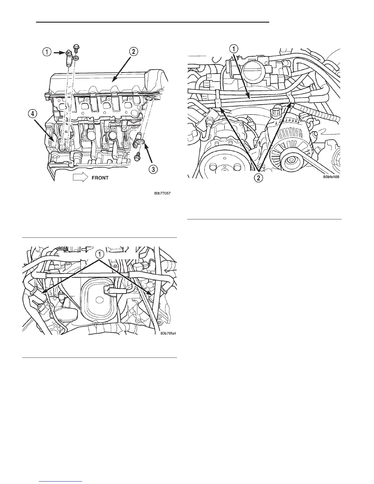
Fig. 43 Crankshaft Position Sensor
1 – CRANKSHAFT POSITION SENSOR
2 – CYLINDER HEAD COVER
3 – CAMSHAFT POSITION SENSOR
4 – RIGHT SIDE CYLINDER BLOCK
Fig. 44 Crankcase Breather Connection Points
1 – CRANKCASE BREATHERS
Fig. 45 Heater Hoses and Tubes Removal /
Installation
1 – HEATER HOSES AND TUBES
2 – ROUTING/RETAINING CLIPS
DN 4.7L ENGINE 9 - 33
REMOVAL AND INSTALLATION (Continued)