(2) Immerse the piston head and rings in clean
engine oil. Position a ring compressor over the piston
and rings. Tighten ring compressor. Ensure posi-
tion of rings do not change during this opera-
tion.
(3) Position bearing onto connecting rod. Ensure
that hole in bearing shell aligns with hole in connect-
ing rod. Lubricate bearing surface with clean engine
oil.
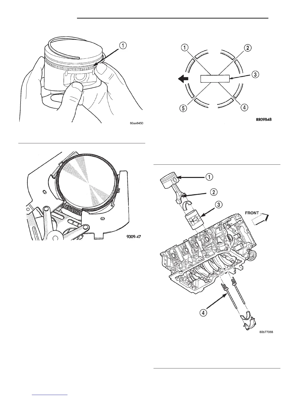
(4) Install Special Tool 8507 Connecting Rod
Guides into connecting rod bolt threads (Fig. 115).
(5) The pistons are marked on the piston pin bore
surface with an raised “F” indicating installation
position. This mark must be pointing toward the
front of engine on both cylinder banks. The connect-
ing rod oil slinger slot faces the front of the engine
(Fig. 116).
(6) Wipe cylinder bore clean and lubricate with
engine oil.
Fig. 112 Side Rail—Installation
1 – SIDE RAIL END
Fig. 113 Upper and Intermediate Rings—Installation
Fig. 114 Piston Ring End Gap Position
1 – SIDE RAIL UPPER
2 – NO. 1 RING GAP
3 – PISTON PIN
4 – SIDE RAIL LOWER
5 – NO. 2 RING GAP AND SPACER EXPANDER GAP
Fig. 115 Piston and Connecting Rod—Installation
1 – “F” TOWARD FRONT OF ENGINE
2 – OIL SLINGER SLOT
3 – RING COMPRESSOR
4 – SPECIAL TOOL 8507
9 - 66 4.7L ENGINE DN
REMOVAL AND INSTALLATION (Continued)