INSTALLATION
Only one main bearing should be selectively fitted
while all other main bearing caps are properly tight-
ened. All bearing capbolts removed during service pro-
cedures are to be cleaned and oiled before installation.
When installing a new upper bearing shell, slightly
chamfer the sharp edges from the plain side.
(1) Start bearing in place, and insert Crankshaft
Main Bearing Remover/Installer Tool C-3059 into oil
hole of crankshaft (Fig. 58).
(2) Slowly rotate crankshaft counterclockwise slid-
ing the bearing into position. Remove Tool C-3059.
(3)
Install the bearing caps. Clean and oil the bolts.
Tighten the capbolts to 115 N·m (85 ft. lbs.) torque.
(4) Install the oil pump.
(5) Install the oil pan.
(6) Start engine check for leaks.
DISTRIBUTOR DRIVE SHAFT BUSHING
REMOVAL
(1) Remove distributor, refer to Group 8D, Ignition
Systems for the proper procedure.
(2) Remove the intake manifold. Refer to Intake
Manifold in this section for correct procedure.
(3) Insert Distributor Drive Shaft Bushing Puller
Tool C-3052 into old bushing and thread down until a
tight fit is obtained (Fig. 59).
(4) Hold puller screw and tighten puller nut until
bushing is removed.
INSTALLATION
(1) Slide new bushing over burnishing end of Dis-
tributor Drive Shaft Bushing Driver/Burnisher Tool
C-3053. Insert the tool and bushing into the bore.
(2) Drive bushing and tool into position, using a
hammer (Fig. 60).
(3) As the burnisher is pulled through the bushing,
the bushing is expanded tight in the block and bur-
nished to correct size (Fig. 61). DO NOT ream this
bushing.
CAUTION: This procedure MUST be followed when
installing a new bushing or seizure to shaft may
occur.
(4) Install the intake manifold.
DISTRIBUTOR INSTALLATION
NOTE: Before installing the distributor, the oil
pump drive shaft must be aligned to number one
cylinder.
(1) Rotate crankshaft until No.1 cylinder is at top
dead center on the firing stroke.
(2) When in this position, the timing mark of
vibration damper should be under “0” on the timing
indicator.
(3) Install the shaft so that after the gear spirals
into place, it will index with the oil pump shaft. The
slot on top of oil pump shaft should be aligned
towards the left front intake manifold attaching bolt
hole (Fig. 62).
(4) Install distributor, refer to Group 8D, Ignition
Systems for the proper procedure.
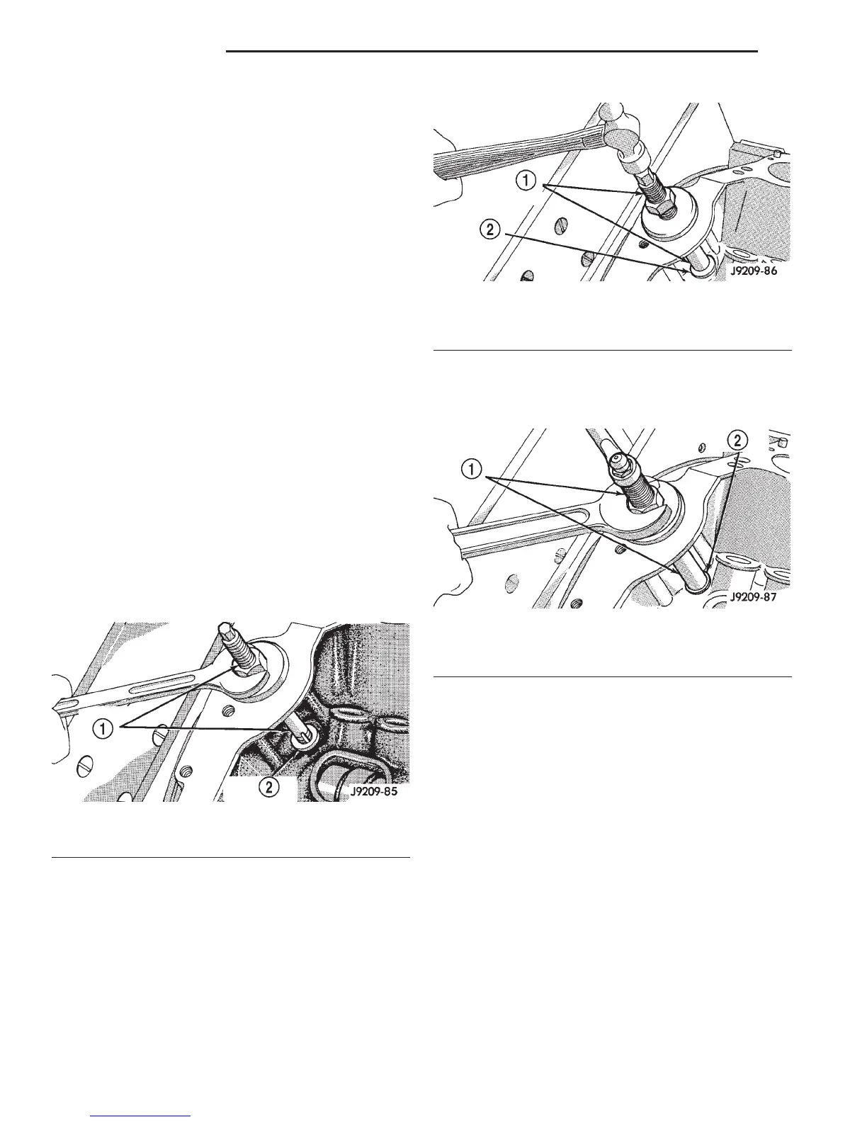
Fig. 59 Distributor Driveshaft Bushing Removal
1 – SPECIAL TOOL C-3052
2 – BUSHING
Fig. 60 Distributor Driveshaft Bushing Installation
1 – SPECIAL TOOL C-3053
2 – BUSHING
Fig. 61 Burnishing Distributor Driveshaft Bushing
1 – SPECIAL TOOL C-3053
2 – BUSHING
9 - 114 5.2L ENGINE DN
REMOVAL AND INSTALLATION (Continued)