Use a 2 step procedure so the valve guides are
reamed true in relation to the valve seat:
• Step 1—Ream to 0.0763 mm (0.003 inch).
• Step 2—Ream to 0.381 mm (0.015 inch).
REFACING VALVES AND VALVE SEATS
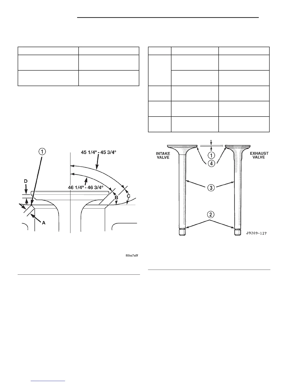
The intake and exhaust valves have a 43-1/4° to
43-3/4° face angle and a 44-1/4° to 44-3/4° seat angle
(Fig. 20).
VALVES
Inspect the remaining margin after the valves are
refaced (Fig. 21). Valves with less than 1.190 mm
(0.047 inch) margin should be discarded.
VALVE SEATS
CAUTION: DO NOT un-shroud valves during valve
seat refacing (Fig. 22).
(1) When refacing valve seats, it is important that
the correct size valve guide pilot be used for reseat-
ing stones. A true and complete surface must be
obtained.
(2) Measure the concentricity of valve seat using a
dial indicator. Total runout should not exceed 0.051
mm (0.002 inch) total indicator reading.
(3) Inspect the valve seat with Prussian blue to
determine where the valve contacts the seat. To do
this, coat valve seat LIGHTLY with Prussian blue
then set valve in place. Rotate the valve with light
pressure. If the blue is transferred to the center of
valve face, contact is satisfactory. If the blue is trans-
ferred to the top edge of valve face, lower valve seat
with a 15° stone. If the blue is transferred to bottom
edge of valve face raise valve seat with a 60° stone.
(4) When seat is properly positioned the width of
intake seats should be 1.016-1.524 mm (0.040-0.060
REAMER SIZES
REAMER O/S VALVE GUIDE SIZE
0.076 mm (0.003 in.) 8.026 - 8.052 mm
(0.316 - 0.317 in.)
0.381 mm (0.015 in.) 8.331 - 8.357 mm
(0.328 - 0.329 in.)
Fig. 20 Valve Face and Seat Angles
1 – CONTACT POINT
VALVE FACE AND VALVE SEAT ANGLE CHART
ITEM DESCRIPTION SPECIFICATION
A SEAT WIDTH– 1.016 - 1.524 mm
INTAKE (0.040 - 0.060 in.)
SEAT WIDTH– 1.524 - 2.032 mm
EXHAUST (0.060 - 0.080 in.)
B FACE ANGLE
(INT. and EXT.) 43
1
⁄
4
°-43
3
⁄
4
°
C SEAT ANGLE
(INT. and EXT.) 44
1
⁄
4
°-44
3
⁄
4
°
D CONTACT
SURFACE —
Fig. 21 Intake and Exhaust Valves
1 – MARGIN
2 – VALVE SPRING RETAINER LOCK GROOVE
3 – STEM
4–FACE
9 - 154 5.9L ENGINE DN
SERVICE PROCEDURES (Continued)