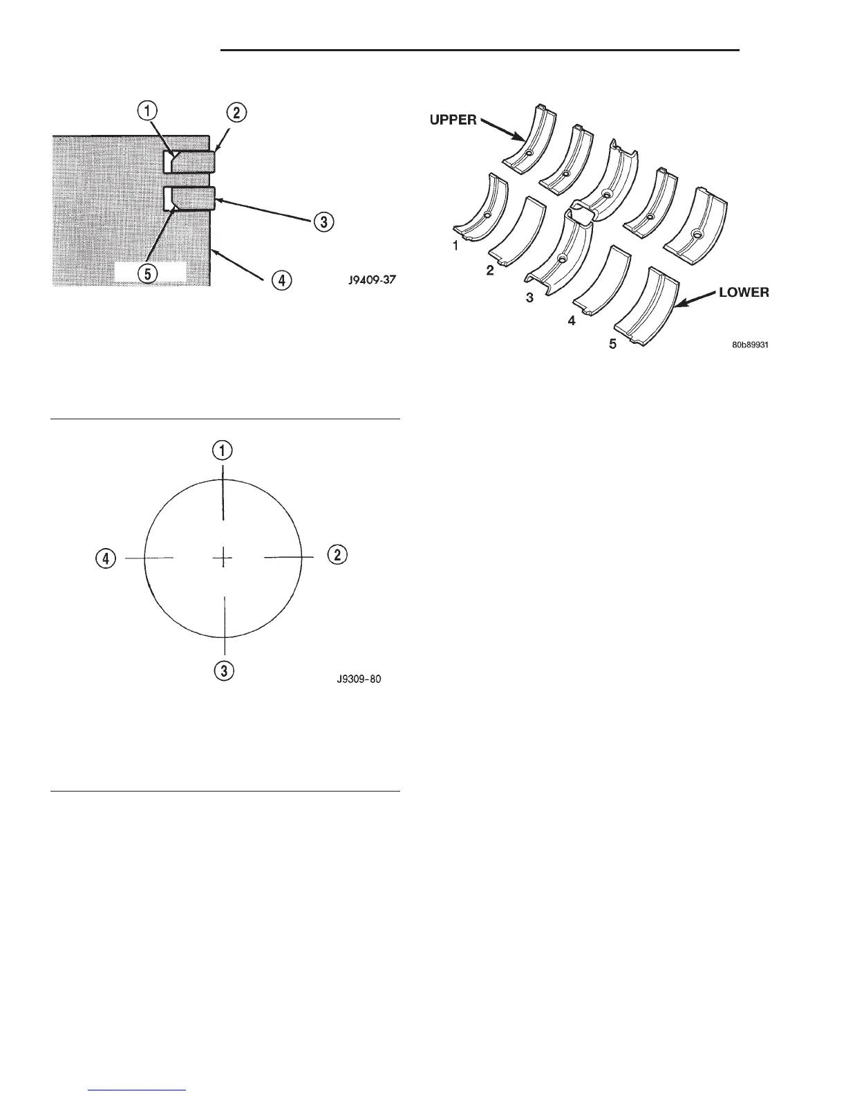
Upper and lower No.3 bearing halves are flanged
to carry the crankshaft thrust loads. They are NOT
interchangeable with any other bearing halves in the
engine (Fig. 31). Bearing shells are available in stan-
dard and the following undersizes: 0.25 mm (0.001
inch), 0.051 mm (0.002 inch), 0.076 mm (0.003 inch),
0.254 mm (0.010 inch) and 0.305 mm (0.012 inch).
Never install an undersize bearing that will reduce
clearance below specifications.
REMOVAL AND INSTALLATION
ENGINE FRONT MOUNTS
REMOVAL—2WD
(1) Disconnect the negative cable from the battery.
(2) Raise hood and position fan to assure clearance
for radiator top tank and hose.
CAUTION: DO NOT lift the engine by the intake
manifold.
(3) Install engine lifting fixture.
(4) Raise vehicle on hoist.
(5) Remove the insulator through bolt (Fig. 32)
(Fig. 33).
(6) Raise engine with lifting fixture SLIGHTLY.
Remove insulator retaining bolts and remove the
insulator assembly.
(7) Remove insulator heat shield and transfer to
new insulator.
INSTALLATION—2WD
(1) With the engine raised SLIGHTLY, position
insulator assembly onto the engine block and install
bolts (Fig. 32) (Fig. 33). Tighten the bolts to 41 N·m
(30 ft. lbs.) torque.
(2) Lower engine with lifting fixture while guiding
insulator assembly into the engine insulator bracket
(Fig. 34).
(3) Install insulator to bracket thru-bolt. Tighten
the thru-bolt nut to 68 N·m (50 ft. lbs.) torque.
(4) Remove lifting fixture.
(5) Connect the negative cable to the battery.
Fig. 29 Compression Ring Chamfer Location
(Typical)
1 – CHAMFER
2 – TOP COMPRESSION RING
3 – SECOND COMPRESSION RING
4 – PISTON
5 – CHAMFER
Fig. 30 Proper Ring Installation
1 – OIL RING SPACER GAP
2 – SECOND COMPRESSION RING GAP OIL RING RAIL GAP
(TOP)
3 – OIL RING RAIL GAP (BOTTOM)
4 – TOP COMPRESSION RING GAP
Fig. 31 Main Bearing Identification
9 - 158 5.9L ENGINE DN
SERVICE PROCEDURES (Continued)