• A sticking tripod joint spider assembly (inner tri-
pod joint only).
• Improper wheel alignment. Refer to Group 2,
Suspension, for alignment checking and setting pro-
cedures and specifications.
VIBRATION AT HIGHWAY SPEEDS
This problem could be a result of:
• Foreign material (mud, etc.) packed on the back-
side of the wheel(s).
• Out of balance front tires or wheels. Refer to
Group 22, Wheels And Tires, for the required balanc-
ing procedure.
• Improper tire and/or wheel runout. Refer to
Group 22, Wheels And Tires, for the required runout
checking procedure.
REMOVAL AND INSTALLATION
FRONT DRIVESHAFT
REMOVAL
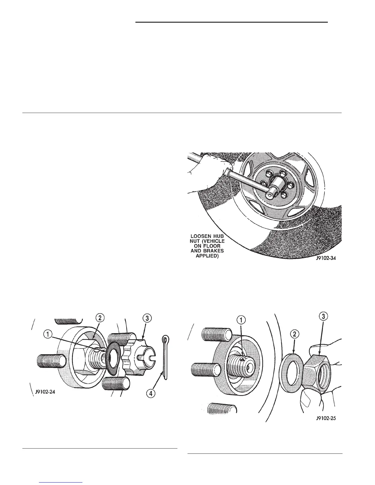
(1) Remove the cotter pin, nut lock, and spring
washer from the stub shaft (Fig. 2).
(2) Loosen the lug nuts and hub nut while the
vehicle is on the surface with the brakes applied (Fig.
3).
(3) Raise the vehicle.
(4) Remove the skid plate, if equipped.
(5) Remove the hub nut and washer from the stub
shaft (Fig. 4).
(6) Remove the wheel and tire.
1 – RETAINER & HOUSING ASM
2 – C-CLIP
3 – TRIPOD JOINT SPIDER
4 – SEAL RETAINING CLAMP
5 – INNER BOOT
6 – SEAL RETAINING CLAMP
7 – C/V JOINT OUTER RACE
8 – C/V JOINT CAGE
9 – C/V JOINT INNER RACE
10 – CHROME ALLOY BALL
11 – RACE RETAINING RING
12 – SEAL RETAINING CLAMP
13 – DRIVE AXLE OUTBOARD SEAL
14 – SEAL RETAINING CLAMP
15 – AXLE SHAFT
16 – RETAINING RING
17 – BALL & ROLLER RETAINER
18 – TRIPOD JOINT BALL
19 – NEEDLE ROLLER
Fig. 2 Cotter Pin, Nut Lock & Spring Washer
Removal
1 – SPRING WASHER
2 – HUB NUT
3 – NUT LOCK
4 – COTTER PIN
Fig. 3 Loosening Wheel Hub Nut
Fig. 4 Hub Nut & Washer
1 – DRIVE SHAFT
2 – HUB WASHER
3 – HUB NUT
3 - 20 FRONT AXLE DRIVESHAFTS DN
DIAGNOSIS AND TESTING (Continued)