the temperature of the fuel tank is above 50° F (10°
C).
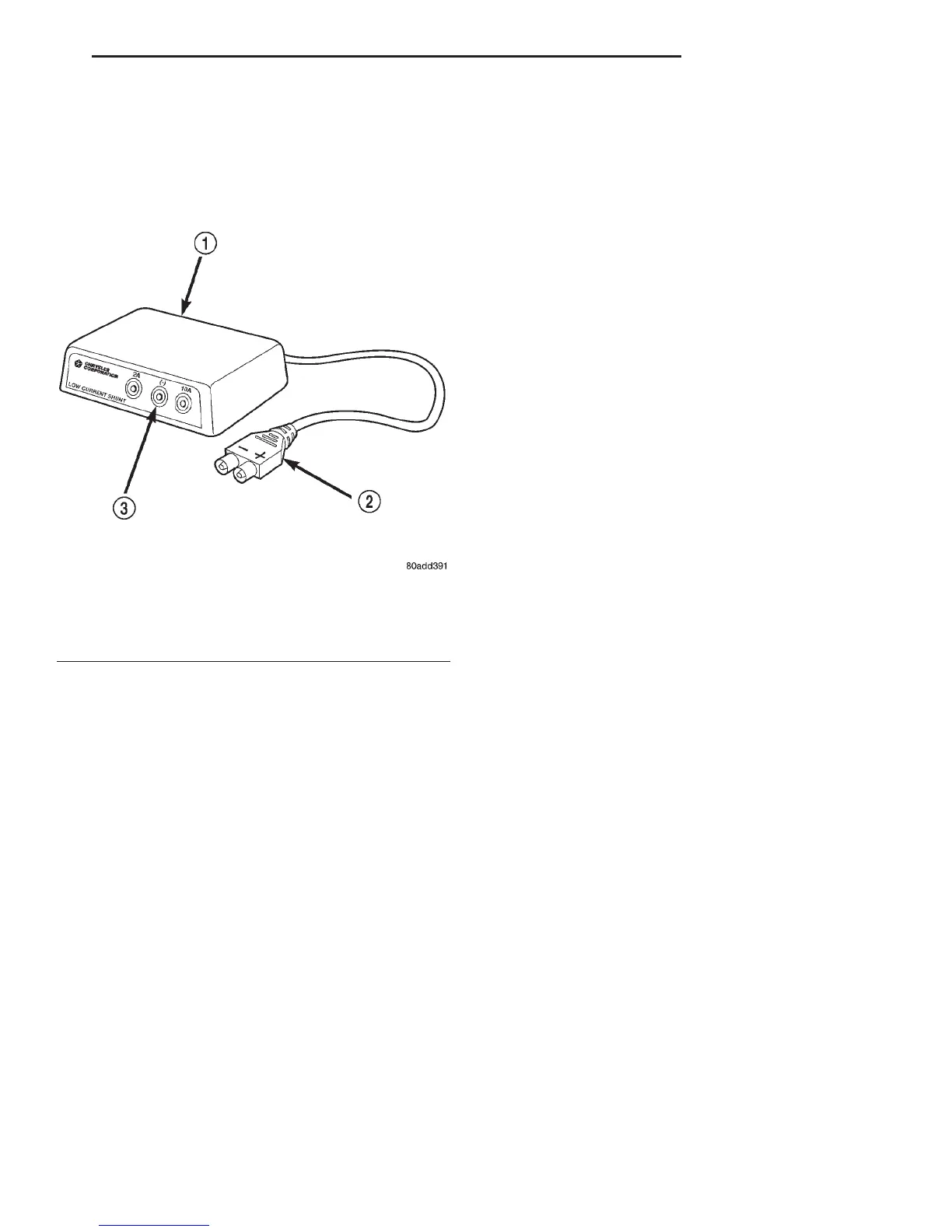
The DRB Scan Tool along with the DRB Low Cur-
rent Shunt (LCS) adapter (Fig. 9) and its test leads
will be used to check fuel pump amperage specifica-
tions.
(1) Obtain LCS adapter.
(2) Plug cable from LCS adapter into DRB scan
tool at SET 1 receptacle.
(3) Plug DRB into vehicle 16–way connector (data
link connector).
(4) Connect (-) and (+) test cable leads into LCS
adapter receptacles. Use 10 amp (10A +) receptacle
and common (-) receptacles.
(5) Gain access to MAIN MENU on DRB screen.
(6) Press DVOM button on DRB.
(7) Using left/right arrow keys, highlight CHAN-
NEL 1 function on DRB screen.
(8) Press ENTER three times.
(9) Using up/down arrow keys, highlight RANGE
on DRB screen (screen will default to 2 amp scale).
(10) Press ENTER to change 2 amp scale to 10
amp scale. This step must be done to prevent
damage to DRB scan tool or LCS adapter
(blown fuse).
(11) Remove cover from Power Distribution Center
(PDC).
(12) Remove fuel pump relay from PDC. Refer to
label on PDC cover for relay location.
WARNING: BEFORE PROCEEDING TO NEXT STEP,
NOTE THE FUEL PUMP WILL BE ACTIVATED AND
SYSTEM PRESSURE WILL BE PRESENT. THIS WILL
OCCUR AFTER CONNECTING TEST LEADS FROM
LCS ADAPTER INTO FUEL PUMP RELAY CAVITIES.
THE FUEL PUMP WILL OPERATE EVEN WITH IGNI-
TION KEY IN OFF POSITION. BEFORE ATTACHING
TEST LEADS, BE SURE ALL FUEL LINES AND FUEL
SYSTEM COMPONENTS ARE CONNECTED.
CAUTION: TO PREVENT POSSIBLE DAMAGE TO
THE VEHICLE ELECTRICAL SYSTEM AND LCS
ADAPTER, THE TEST LEADS MUST BE CON-
NECTED INTO RELAY CAVITIES EXACTLY AS
SHOWN IN FOLLOWING STEPS.
Depending upon vehicle model, year or engine con-
figuration, three different types of relays may be
used: Type-1, type-2 and type–3.
(13) If equipped with type–1 relay (Fig. 10),
attach test leads from LCS adapter into PDC relay
cavities number 30 and 87. For location of these cav-
ities, refer to numbers stamped to bottom of relay
(Fig. 10).
(14) If equipped with type–2 relay (Fig. 11),
attach test leads from LCS adapter into PDC relay
cavities number 30 and 87. For location of these cav-
ities, refer to numbers stamped to bottom of relay
(Fig. 11).
(15) If equipped with type–3 relay (Fig. 12),
attach test leads from LCS adapter into PDC relay
cavities number 3 and 5. For location of these cavi-
ties, refer to numbers stamped to bottom of relay
(Fig. 12).
(16) When LCS adapter test leads are attached
into relay cavities, fuel pump will be activated.
Determine fuel pump amperage on DRB screen.
Amperage should be below 10.0 amps. If amperage is
below 10.0 amps, and specifications for the Fuel
Pump Pressure, Fuel Pump Capacity and Fuel Pres-
sure Leak Down tests were met, the fuel pump mod-
ule is OK.
(17) If amperage is more than 10.0 amps, replace
fuel pump module assembly. The electric fuel pump
is not serviced separately.
(18) Disconnect test leads from relay cavities
immediately after testing.
FUEL GAUGE SENDING UNIT
The fuel gauge sending unit contains a variable
resistor (track). As the float moves up or down, elec-
trical resistance will change. Refer to Group 8E,
Instrument Panel and Gauges for Fuel Gauge test-
ing. To test the gauge sending unit only, it must be
removed from vehicle. The unit is part of the fuel
pump module. Refer to Fuel Pump Module Removal/
Fig. 9 Low Current Shunt Adapter
1 – LOW CURRENT SHUNT ADAPTER
2 – PLUG TO DRB
3 – TEST LEAD RECEPTACLES
DN FUEL SYSTEM 14 - 9
DIAGNOSIS AND TESTING (Continued)