INSTALLATION
(1) If fuel pump module is being installed, refer to
Fuel Pump Module Removal/Installation. Be sure
fuel filter/fuel pressure regulator inlet fitting is
pointed towards front of vehicle.
(2) Place and secure fuel tank on top of transmis-
sion jack.
(3) Raise tank up enough to connect fuel line, elec-
trical connector and both EVAP lines to top of fuel
tank. Refer to Quick-Connect Fittings for fuel line
procedures.
(4) Continue raising tank into position and install
mounting straps and nuts. Tighten nuts to 27–54
N·m (20–40 ft. lbs.) torque. Do not over tighten
mounting strap nuts.
(5) Remove transmission jack.
(6) Connect fill/vent hoses to fill/vent tube assem-
bly.
(7) Tighten hose clamps at fill/vent hoses.
(8) If equipped, install fuel tank skid plate. Refer
to Fuel Tank Skid Plate in Group 23, Body.
(9) Connect negative cable to battery.
(10) Refill fuel tank and install fill cap.
(11) Inspect all hoses and lines for leaks.
FUEL TANK FILLER TUBE CAP
REMOVAL/INSTALLATION
If replacement of the 1/4 turn fuel tank filler tube
cap is necessary, it must be replaced with an identi-
cal cap to be sure of correct system operation.
CAUTION: Remove the fuel tank filler tube cap to
relieve fuel tank pressure. The cap must be
removed prior to disconnecting any fuel system
component or before draining the fuel tank.
ACCELERATOR PEDAL
All engines are equipped with torsion return
springs located on the throttle body shaft. 3.9L V-6
and 5.2/5.9L V-8 engines equipped with a manual
transmission have an additional pedal return spring
on the throttle body linkage.
REMOVAL
CAUTION: Be careful not to damage or kink the
cable core wire (within the cable sheathing) while
servicing accelerator pedal or cables.
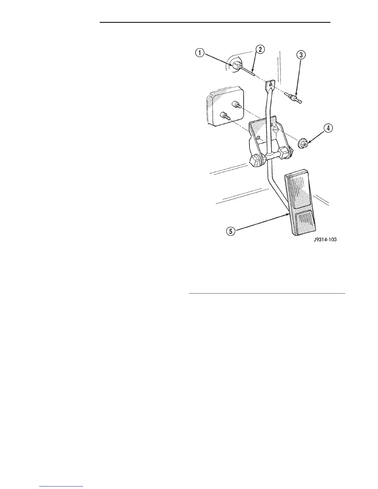
(1) From inside the vehicle, hold up accelerator
pedal. Remove plastic cable retainer and throttle
cable core wire from upper end of pedal arm (Fig.
38). Plastic cable retainer snaps into pedal arm.
(2) Remove two accelerator pedal/bracket nuts
(Fig. 38) and remove pedal/bracket assembly from
vehicle.
INSTALLATION
(1) Position pedal/bracket assembly over the two
dash panel mounting studs and install retaining
nuts.
(2) Tighten nuts to 7 N·m (65 in. lbs.) torque.
(3) From inside the vehicle, hold up the accelerator
pedal. Install the throttle cable core wire and plastic
cable retainer into the upper end of the pedal arm.
The plastic retainer is snapped into the pedal arm.
When installing the plastic retainer to the accelera-
tor pedal arm, note the index tab on the pedal arm
(Fig. 39). Align the index slot (Fig. 39) on the plastic
cable retainer to this index tab.
Fig. 38 Accelerator Pedal—Removal or Installation
1 – PINCH SIDES
2 – CABLE
3 – CABLE RETAINER
4 – NUTS (2)
5 – ACCELERATOR PEDAL
14 - 22 FUEL SYSTEM DN
REMOVAL AND INSTALLATION (Continued)