(2) Position sensor to throttle body while guiding
rubber fitting over throttle body vacuum nipple.
(3) Install MAP sensor mounting bolts (screws).
Tighten screws to 3 N·m (25 in. lbs.) torque.
(4) Install air duct at throttle body.
MANIFOLD ABSOLUTE PRESSURE (MAP)
SENSOR—4.7L V–8 ENGINE
The MAP sensor is located on the front of the
intake manifold (Fig. 28). An o-ring seals the sensor
to the intake manifold.
REMOVAL
(1) Disconnect electrical connector at sensor.
(2) Clean area around MAP sensor.
(3) Remove 2 sensor mounting bolts (Fig. 28).
(4) Remove MAP sensor from intake manifold.
INSTALLATION
(1) Clean MAP sensor mounting hole at intake
manifold.
(2) Check MAP sensor o-ring seal for cuts or tears.
(3) Position sensor into manifold.
(4) Install MAP sensor mounting bolts (screws).
Tighten screws to 3 N·m (25 in. lbs.) torque.
(5) Connect electrical connector.
POWERTRAIN CONTROL MODULE (PCM)
The PCM is located in the engine compartment
(Fig. 29).
REMOVAL
To avoid possible voltage spike damage to the
PCM, ignition key must be off, and negative battery
cable must be disconnected before unplugging PCM
connectors.
(1) Disconnect negative battery cable at battery.
(2) Remove cover over electrical connectors. Cover
snaps onto PCM.
(3) Carefully unplug the three 32–way connectors
from PCM.
(4) Remove three PCM mounting bolts and remove
PCM from vehicle.
INSTALLATION
(1) Install PCM and mounting bolts to vehicle.
(2) Tighten bolts to 3–5 N·m (30–40 in. lbs.).
(3) Check pin connectors in the PCM and the three
32–way connectors for corrosion or damage. Repair
as necessary.
(4) Install three 32–way connectors.
(5) Install cover over electrical connectors. Cover
snaps onto PCM.
(6) Install battery cable.
(7) Use the DRB scan tool to reprogram new PCM
with vehicles original Identification Number (VIN)
and original vehicle mileage. If this step is not done,
a Diagnostic Trouble Code (DTC) may be set.
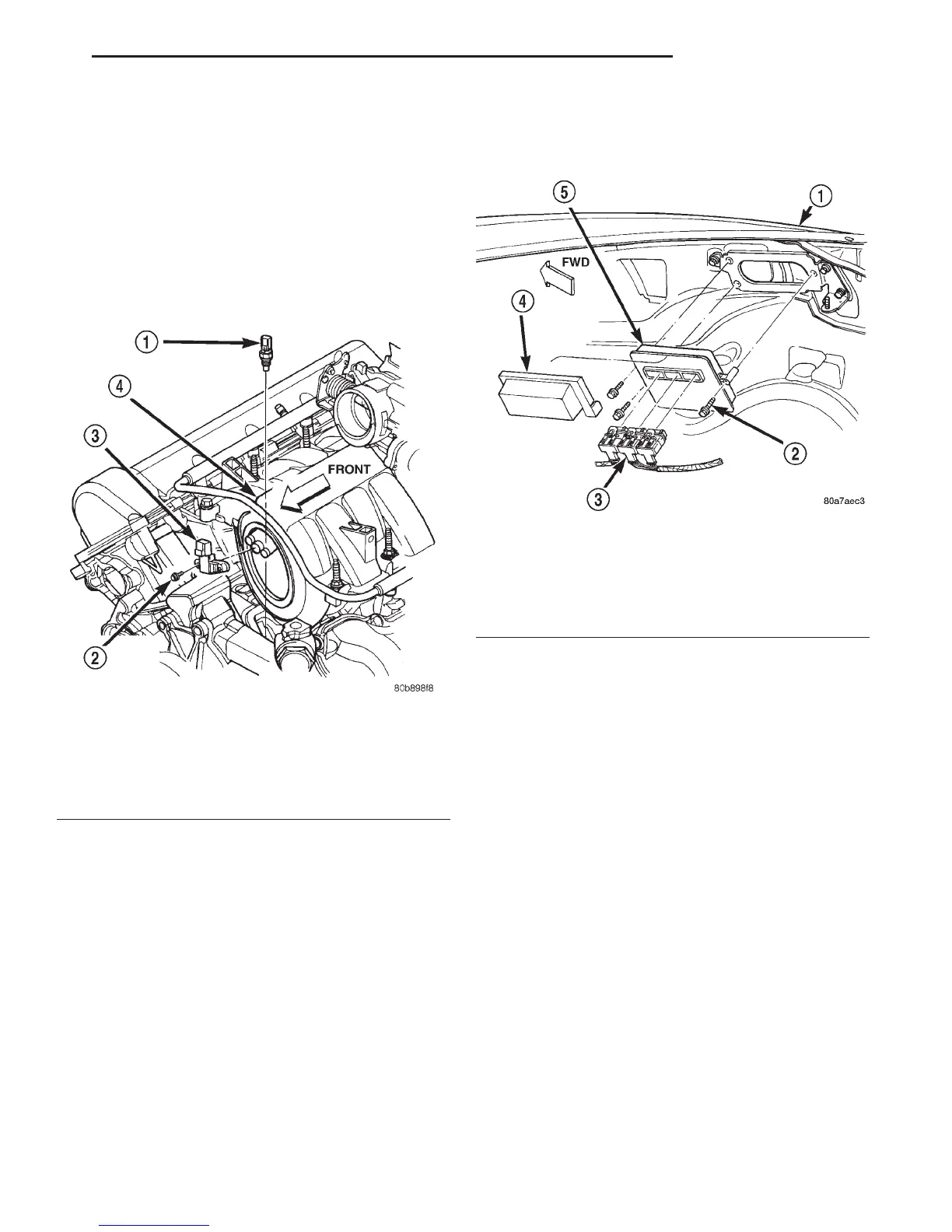
Fig. 28 MAP and ECT Sensor Locations—4.7L V–8
Engine
1 – ECT SENSOR
2 – MOUNTING BOLTS (2)
3 – MAP SENSOR
4 – INTAKE MANIFOLD
Fig. 29 PCM Location and Mounting
1 – RIGHT FRONT FENDER
2 – PCM MOUNTING BOLTS (3)
3 – 32–WAY CONNECTORS (3)
4 – COVER
5 – POWERTRAIN CONTROL MODULE (PCM)
DN FUEL SYSTEM 14 - 49
REMOVAL AND INSTALLATION (Continued)