RACK & PINION STEERING GEAR
TABLE OF CONTENTS
page page
DESCRIPTION AND OPERATION
RACK & PINION STEERING GEAR ...........11
REMOVAL AND INSTALLATION
TIERODEND ...........................11
RACK & PINION STEERING GEAR - 4x2 .......12
RACK & PINION STEERING GEAR - 4x4 .......12
DISASSEMBLY AND ASSEMBLY
BOOT SEAL.............................14
SPECIFICATIONS
TORQUE CHART .........................14
SPECIAL TOOLS
RACK & PINION STEERING GEAR ...........14
DESCRIPTION AND OPERATION
RACK & PINION STEERING GEAR
DESCRIPTION
A rack and pinion steering gears (Fig. 1) is made
up of two main components, the pinon shaft and the
rack. The gear cannot be adjusted or internally ser-
viced. If a malfunction or a fluid leak occurs, the gear
must be replaced as an assembly. If a boot seal
becomes damaged, the steering gear must be
removed to replace the boot seal.
OPERATION
The steering column shaft is attached to the gear
pinion. The rotation of the pinion moves the gear
rack from side-to-side. This lateral action of the rack
pushes and pulls the tie rods to change the direction
of the front wheels.
REMOVAL AND INSTALLATION
TIE ROD END
REMOVAL
(1) Raise and support the vehicle.
(2) Remove the nut from the tie rod end.
(3) Separate the tie rod end from the steering
knuckle with Puller C-3894-A.
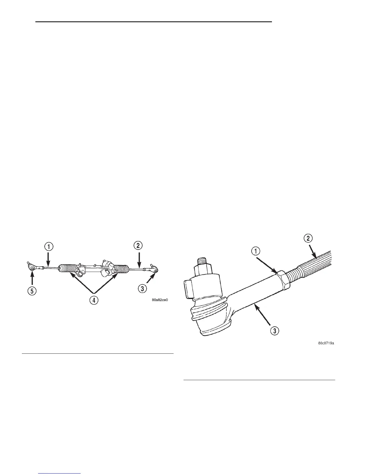
(4) Loosen the jam nut (Fig. 2) and unthread the
tie rod end.
INSTALLATION
(1) Thread the tie rod end onto the tie rod.
(2) Clean the tie rod end stud and knuckle taper.
(3) Install the tie rod end stud into the steering
knuckle and tighten the nut to 108 N·m (80 ft. lbs.).
(4) Tighten the jam nut to 75 N·m (55 ft. lbs.).
NOTE: Do not twist boot while tighten the jam nut.
Fig. 1 Rack & Pinion Steering Gear
1 – TIE ROD
2 – TIE ROD
3 – TIE ROD END
4 – BOOTS
5 – TIE ROD END
Fig. 2 Tie Rod End
1 – JAM NUT
2 – TIE ROD
3 – TIE ROD END
DN STEERING 19 - 11