(10) Remove the turn signal multi-function switch
connector witha7mmsocket (Fig. 8).
(11) Remove remaining electrical connections from
the column switches (Fig. 8).
(12) Remove the bolt and nut from upper interme-
diate shaft (Fig. 9). Slide upper intermediate shaft off
column shaft.
(13) Remove column mounting nuts (Fig. 10).
(14) Remove column from vehicle.
(15) Remove clockspring, switches and key cylin-
der, refer to Group 8 Electrical for procedures.
CAUTION: Failure to follow Group 8 Electrical pro-
cedure for clockspring removal, may damage the
clockspring plastic latches.
INSTALLATION
(1) Install switches, clockspring and key cylinder,
refer to Group 8 Electrical for procedures.
(2) Position the column to the panel bracket and
attaching studs. Install, but loose assemble the
mounting nuts.
(3) Slide upper intermediate shaft onto the column
shaft. Install a new bolt and nut and tighten to 49
N·m (36 ft. lbs.).
(4) Tighten column mounting nuts to 12 N·m (105
in. lbs.).
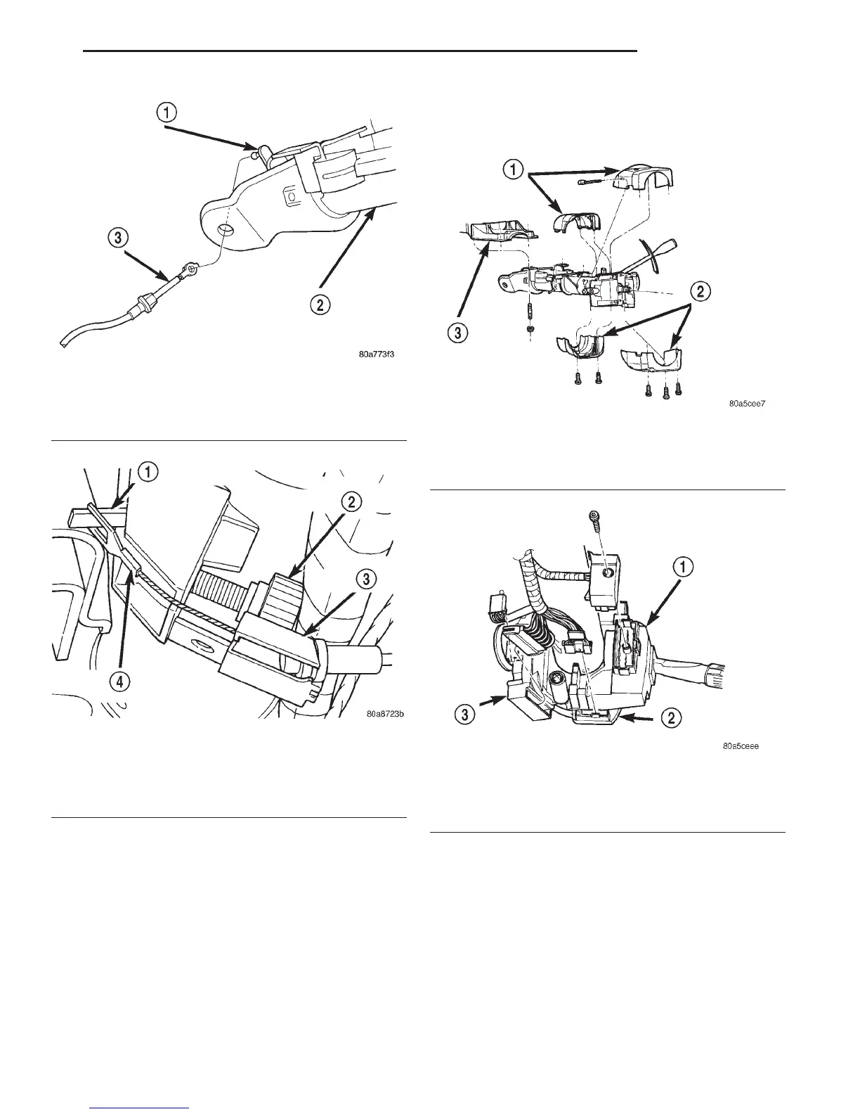
Fig. 5 Shift Cable
1 – SHIFT LEVER
2 – STEERING COLUMN
3 – SHIFT CABLE
Fig. 6 PRNDL Drive Cable
1 – PRNDL LEVER
2 – THUMB SCREW
3 – CABLE RETAINER
4 – PRNDL CABLE
Fig. 7 Column Shrouds
1 – UPPER SHROUD
2 – LOWER SHROUD
3 – PANEL BRACKET
Fig. 8 Multi-function Switch & Column Wiring
1 – MULTI-FUNCTION SWITCH
2 – SPEED CONTROL
3 – IGNITION SWITCH
DN STEERING 19 - 17
REMOVAL AND INSTALLATION (Continued)