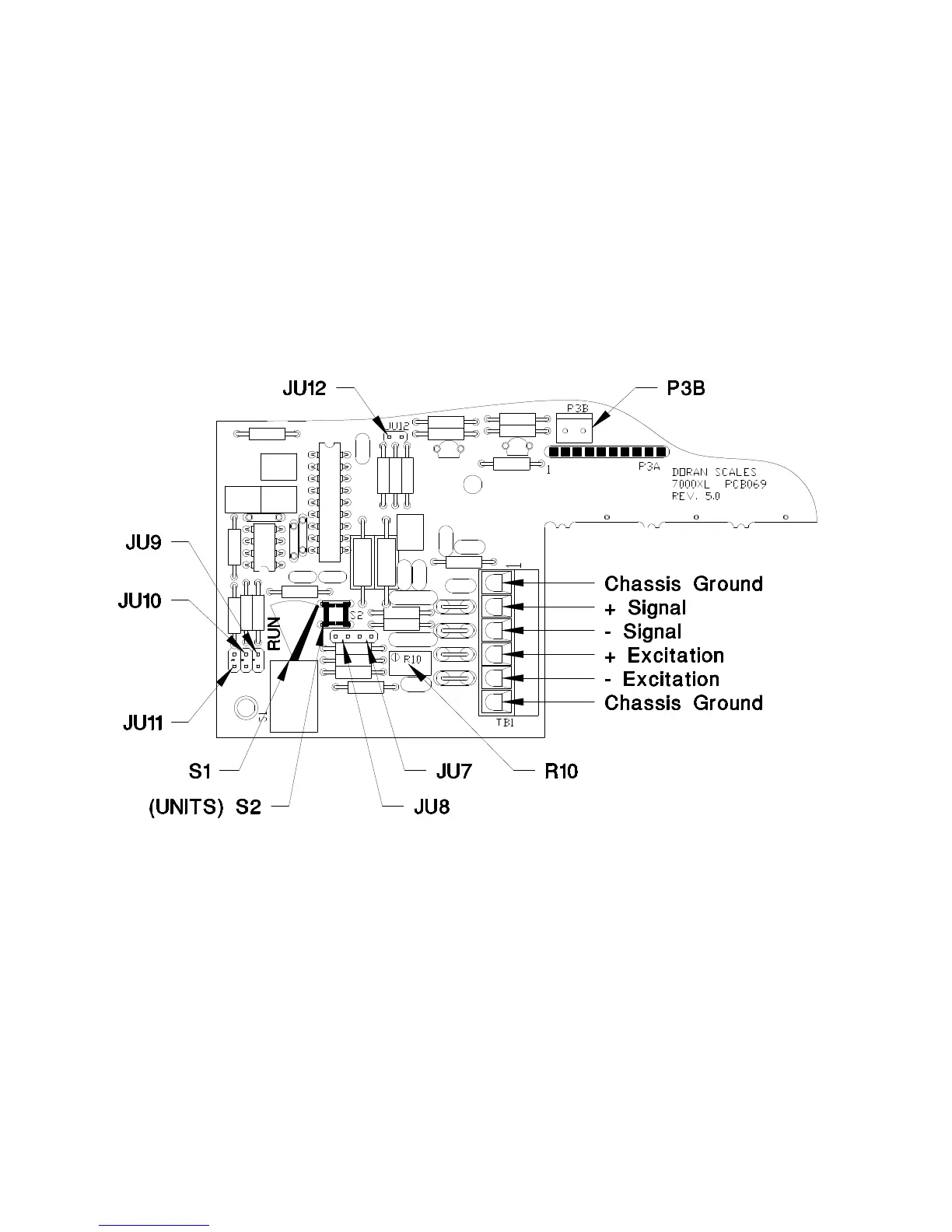
Section 3. Quick Setup Guide
Load Cell:
Load cell connections are made through a terminal block located on the
main PC. board. This block can be accessed by removing the rear cover.
The Calibration switch S1, the auxiliary UNITS switch S2 and the zero
offset adjustment are located behind the Calibration Access Cover.
Calibration and setup can be performed by removing the Calibration
access cover. Access to the Load Cell connections require the removal of
the rear cover. Switch S2 performs the same function as the UNITS
switch on the front of the 7000XL.
Fig. 1: Load Cell Connection and Calibration Jumpers
Option Connections:
The Remote Switch and Serial Communications connector is found on the
on the main PC. board. This connection is accessed by removing the rear
cover. Connections are made by either crimping (or soldering) a
connector contact onto each lead of the option cable. After crimping (or
soldering), the contact is pressed into a connector housing. The
completed option connector is then snapped onto the option connector
found on the main board. Like the load cell cable and power cord, the
option cables are passed through watertight fittings mounted on the rear
cover.
10