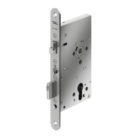
5. Put the thumbturn (T) in a vertical position. Assemble 3
spacers (S) on the door (for recent models only). Place the
inside trim assembly on the door
so that the upper and
lower spindles (F) and (G) engage the thumbturn and the
inside lever. Fasten to the outside housing using the three
1/8" hex drive mounting screws (I). Install the screws
without tightening. Verify the inside lever and thumb-
turn operates smoothly. If not move the inside and
outside housings slightly. Then tighten the screws.
Connect cables to corresponding connectors where
applicable and put excess cables in hole (H) in the
door when installing the inside trim assembly (E) on the
door.
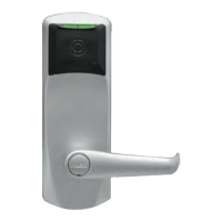
6.
Insert the battery holder into the outside housing
and secure it using the 6-32 x 5/16" (7.9mm) Torx
drive screw (C2) for E-760/770/79/RT Series or 6-32
spanner drive screws for the 660 Series.
The battery holder shall be installed after connecting all
wires to their corresponding connectors, otherwise there is
a risk for battery drain.
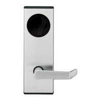
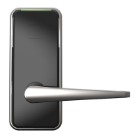
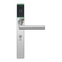
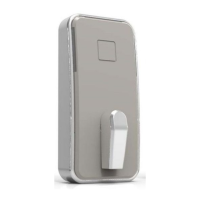
For the E7900 lock series, follow indications stated in step 5
using the illustration below.
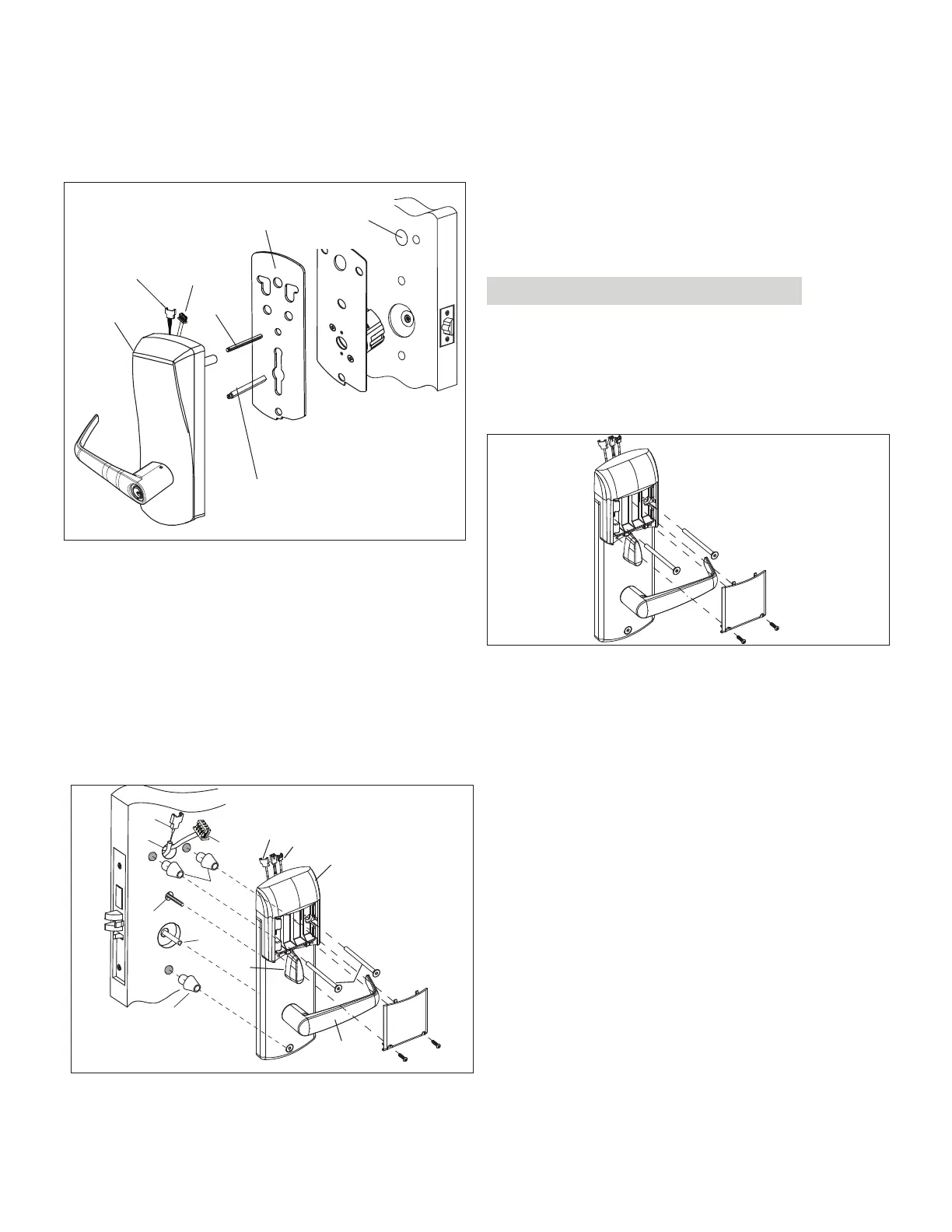
APPENDIX B Installing Cylindrical Models 2-3/8"
& 2-3/4" Backset
B
N
Cylindrical Plate Assembly
F
G
W
W
Place all cables
through H1
hole
W
W
H1
V
F
G
V
W
W
Y
T
I
E3
49
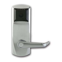
E7900 Series
KD10114-E-1122
 Loading...