20
ED900 09-2021DL4617-001
dormakaba ED900 Setup and Troubleshooting Instructions Chapter 10
. Power on
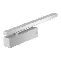
Fig. 10.3.2 Power switch
Fig. 10.3.1 Mode switch
2 Power switch
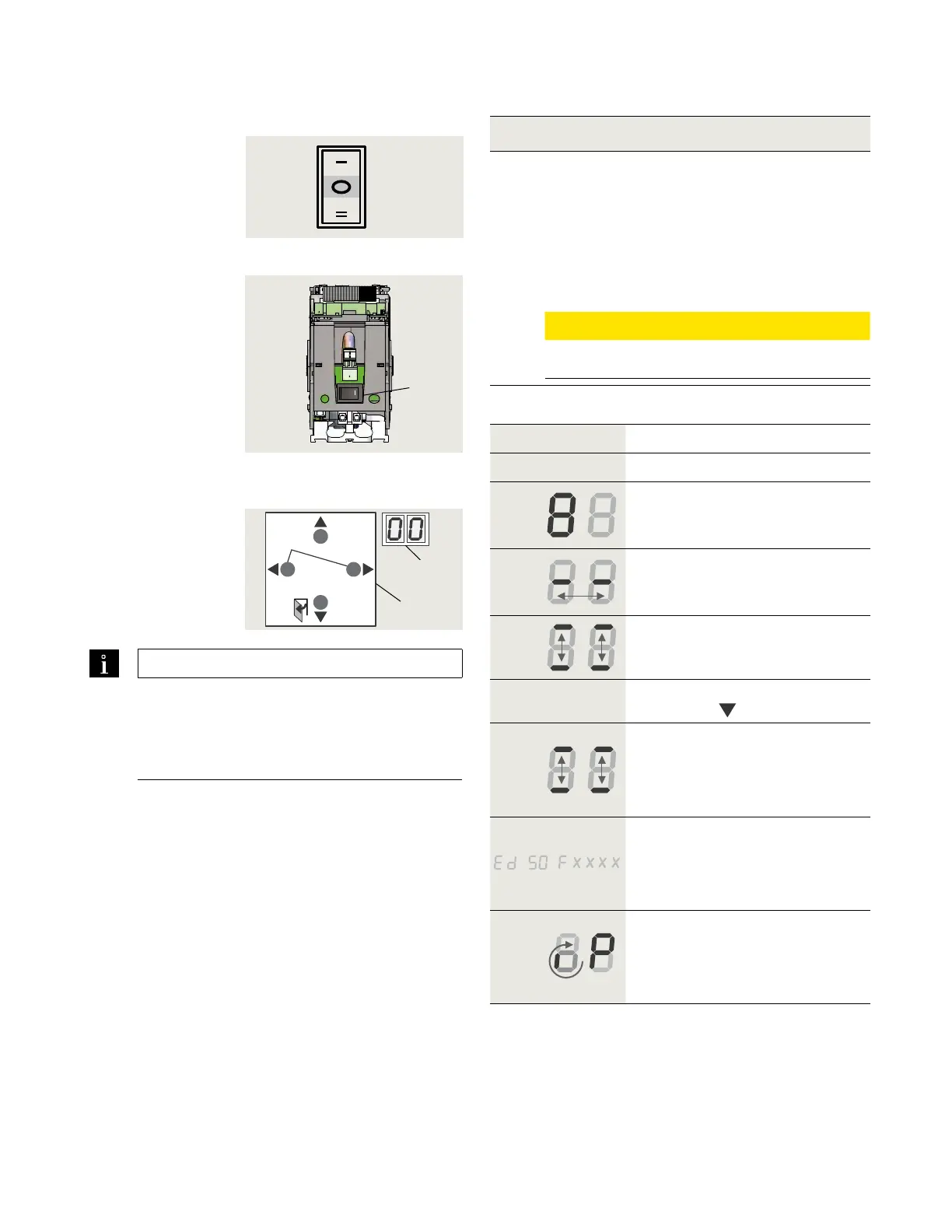
Fig. 10.3.3 4 button keypad,
2 digit display
3 Four button
keypad
4 Two digit display
1 Mode switch,
3 position
o
2
4
3
> 3s Reset
< 3s Quit
> 3s
PRG
< 3s
LEARN
Fact-Setup
> 3s
> 8s
Conditions prior to power on.
. ED operator is installed.
. Standard push arm or arm with track is installed.
. Key switches and other separately supplied
hardware are installed and connected to operator.
. Vac branch circuit to operator is energized.
. Operator motor is cold.
CAUTION
Motor must be cold for commissioning!
Step
Mode switch to CLOSE position.
Step
Power switch to ON position.
System check.
• Series of letters and numbers
rapidly displayed.
Control unit self check.
• Two segments jumping back
and forth.
Horizontal dashes move up and
down.
Step
Press button keypad
down button
.
While digit display segments
move up and down, letters and
numbers will change if required
to display correct orientation.
Display scrolls:
• Device ID (Ed ) as example.
• Firmware version
(format F x x x x)
Program mode display.
Program mode will be displayed
indicating system requires further
parameter settings.
TIPS AND RECOMMENDATIONS
If pressing down button (Step ) does not
result in desired display orientation,
return to Step , turn power button off, then
on to repeat commissioning steps.
.. Power On.
Close