29
ED900 09-2021DL4617-001
dormakaba ED900 Setup and Troubleshooting Instructions Chapter 11
Step
Press
Press and hold PRG > s to enter
program mode, AS parameter
displayed.
Step
Press
Scroll to dL parameter.
Step
Press
Displays "" , factory setting.
Step
Press
"" starts flashing.
.. Inactive door, set parameter dL.
. Set program switch to CLOSE.
. Set parameter dL (door type) for inactive door.
Step
Press
Scroll to select parameter value
("" as an example).
Step
Press
Saves value entered. Display stops
flashing.
Step
Press
Returns to door type parameter.
Step
Press
Exits program mode. Operator is ready
for operation.
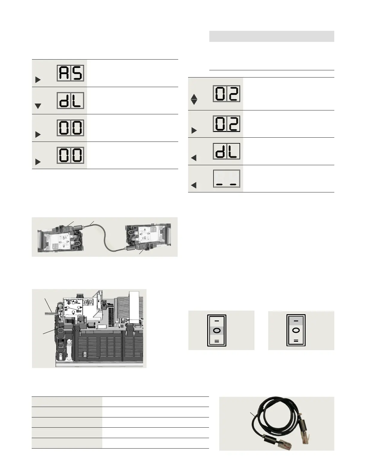
. Connect sync cable between operators
Fig. 11.3.1 Pair door operators, sync cable
1 RJ45 jack
(horizontal) for
Sync cable
.. Install Sync cable.
. Set Mode switch to CLOSE.
. Connect sync cable to active and inactive operator
RJ jacks.
. Secure cable to header.
.. Test door operation.
. Set Mode switch to AUTO.
. Test double door operation.
• Use knowing act device.
Fig. 11.3.4 Mode switch,
AUTO position
1
4
Fig. 11.3.2 RJ45 jack
1 RJ45 jack
4 Mode switch cable
1
1
2
NOTICE
Pairs must be:
• (active) and (inactive) or
• (active) and (inactive).
Sync cable Length Item # Quantity
HX- " [ mm]
Optional
HX- /" [ mm]
HX- /" [ mm]
1
Fig. 11.3.5 Sync cable
.. Sync cable lengths.
2 Sync cable
DX3485-0X0
Fig. 11.3.3 Mode switch,
Close position
Close
Auto