W2940305 Rev 07 8/2019 Dover Fueling Solutions 53
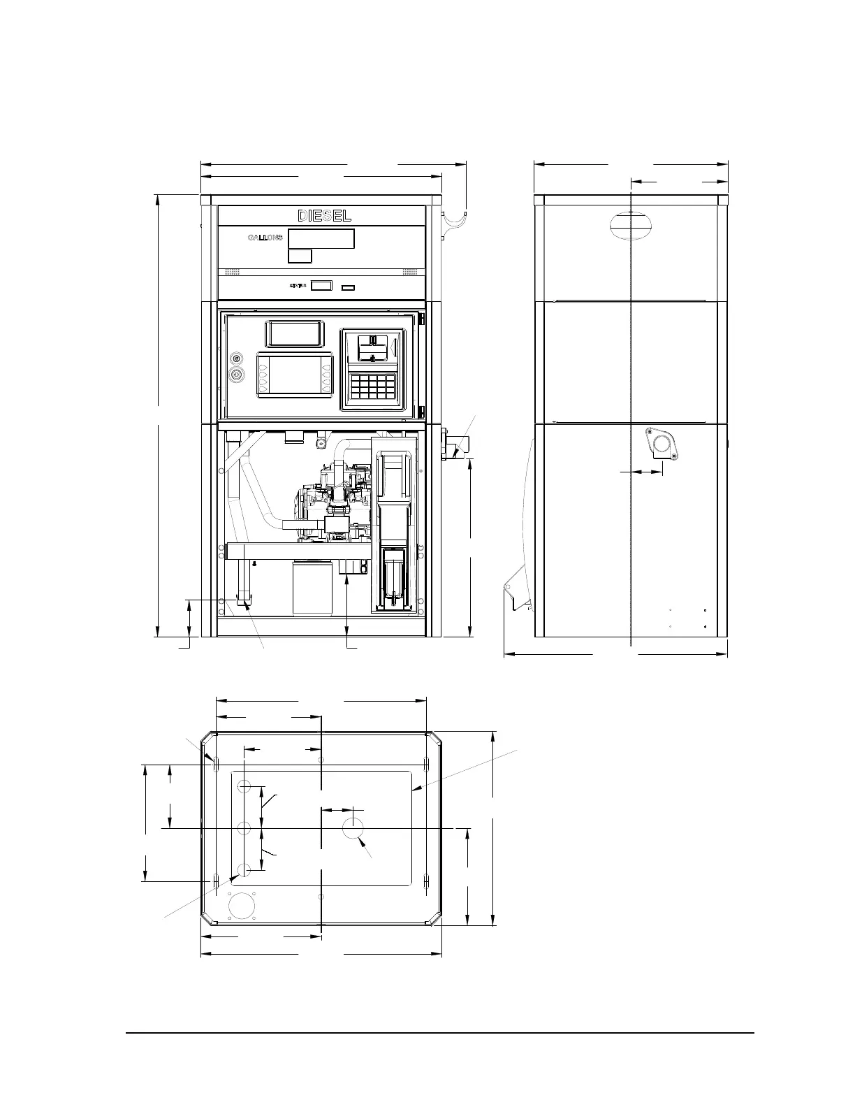
Top View of Base
3 7/8 in.
[100.0 mm]
3 in.
[76.2 mm]
3 7/8 in.
[100.0 mm]
7 1/4 in.
[184.6 mm]
6 in.
[152.4 mm]
11 in.
[279.4 mm]
9 7/8 in.
[251.4 mm]
19 3/4 in.
[503.1 mm]
11 3/8 in.
[289.0 mm]
22 3/4 in.
[578.0 mm]
9 1/8 in.
[232.5 mm]
18 1/4 in.
[465.0 mm]
Front of Dispenser
1-1/2" NPT Inlet
7/16" x 1-7/16"
Mounting Holes
(4 Places)
3/4" Conduits
(2 or 3 Provided)
Note: The interior
dimensions of the
dispenser provide a
maximum rectangular area
of 10-3/4" x 17" for
containment sumps.
41 5/8 in.
[1057.5 mm]
16 3/4 in.
[426.3 mm]
6 in.
[151.2 mm]
2 7/8 in.
[74.6 mm]
22 3/4 in.
[578.0 mm]
25 in.
[636.6 mm]
18 1/4 in.
[465.0 mm]
Standard
Outlet Shown
1" NPT
3 1/2 in.
[88.5 mm]
3/4" Conduits
21 in.
[533.6 mm]
9 1/8 in.
[232.5 mm]
Note: The iMeter is shown
in cabinet. For E85
models the dispenser uses
an Xflow meter. The inlet
and outlet remains at the
same place as shown for
the iMeter.
Models: 3/G7107D/R/Dx or Tx Single–Sided Display, iX Fleet or T7 – Lane
E3/G7107D/R/Dx or Tx Single–Sided Display, E85, iX Fleet or T7 – Lane