Instructions for use Polaris 600 85
Maintenance
1 Carry out a function test.
2 Push the panel (3) forwards and insert 2 snap
lugs (2) into the cover by hand.
3 Insert a slotted screwdriver into the opening
(4), press the panel (3) upwards slightly and
guide the snap-in hook (1) into the cover.
4 Move the spring arm up and down and check
that the panel (3) is securely seated.
The snap-in hook (1) must sit in the cover.
– The panels must slide in the lateral guides
without jamming.
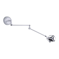
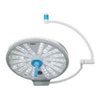
Adjusting the gimbal mounting
The gimbal mounting is set correctly when the light
head is stable in any position and does not move
on its own.
To achieve this, the braking force can be
adjusted on the joint (A) and on the
intermediate joint (B).
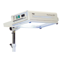
Adjusting the braking force at the joint
1 Adjust the braking force on the joint using the
set screw (A).
Use an Allen key (size 4 mm) for this.
Turn the set screw clockwise to increase the
braking force.
Turn the set screw counterclockwise to
decrease the braking force.
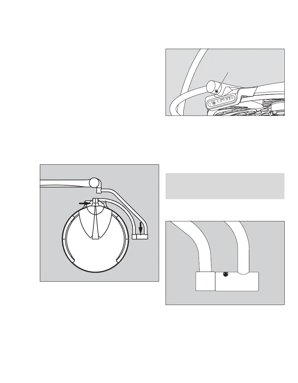
Adjusting the braking force at the intermediate
joint
1 Adjust the braking force on the joint using the
set screw (A).
Use an Allen key (size 4 mm) for this.
2 Adjust the braking force of the joint using the
set screw (A).
27204
28275
NOTE
Set the braking force as low as possible and as
high as necessary.
27205
 Loading...