Maintenance
86 Instructions for use Polaris 600
Turn the set screw clockwise to increase the
braking force.
Turn the set screw counterclockwise to
decrease the braking force.
Checking the locking devices on the arm system
Checking the locking devices on the C
swivel arm and the S swivel arm
– Remove/fit the locking devices in accordance
with the technical documentation.
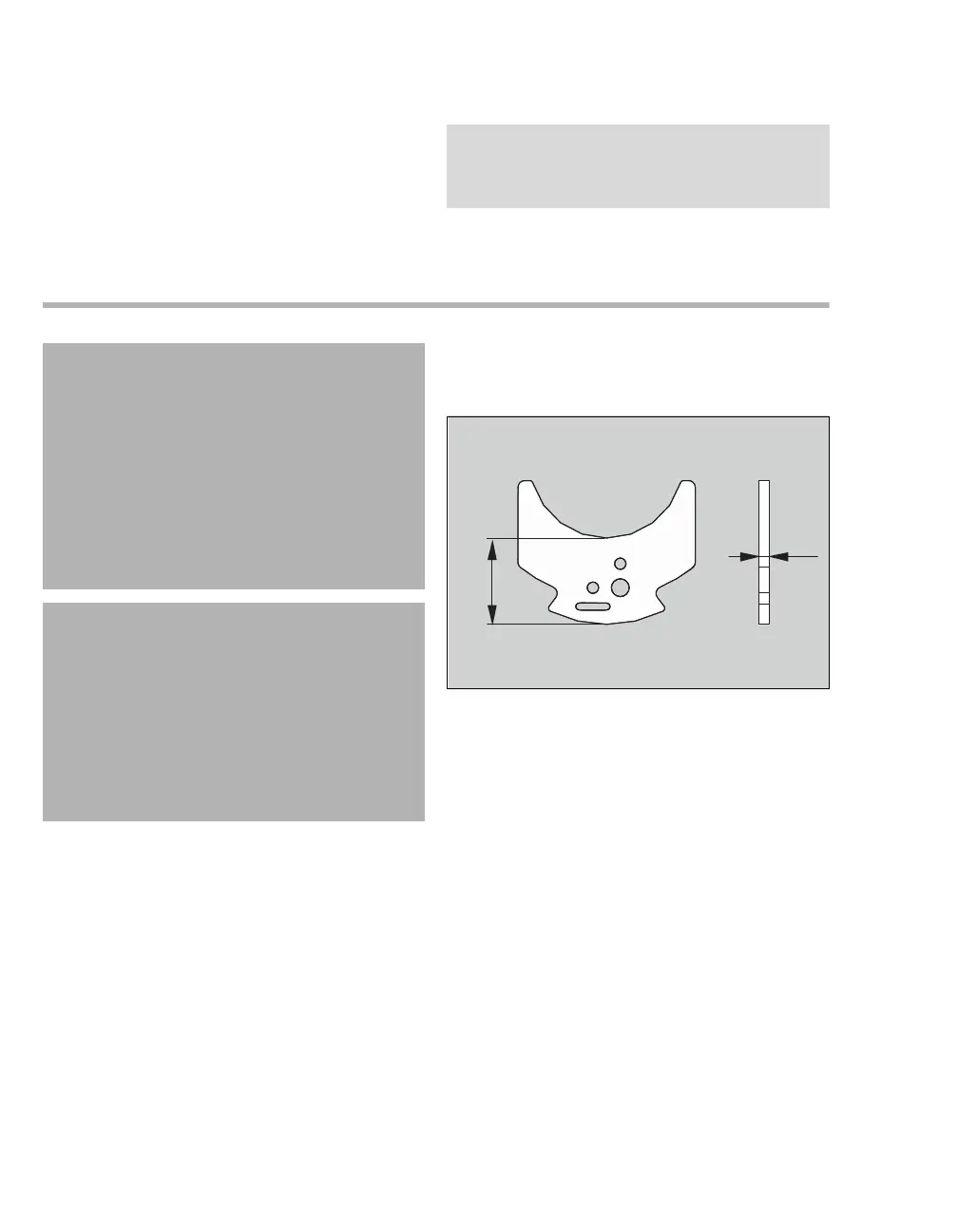
The 2 locking devices on each swivel arm must
be checked for length and material thickness.
The locking device must be replaced if it does
not meet specifications.
The length (A) of the locking device must be at
least 24.5 mm (0.965 in).
The material thickness (B) of the locking device
must be at least 2.1 mm (0.083 in).
Grease the 2 locking devices on each swivel
arm with microGLEIT GP 360 paste.
NOTE
Set the braking force as low as possible and as
high as necessary.
WARNING
Risk of personal injury and property damage
A light/display mount may only be fitted or
removed when the spring arm is prevented
from bouncing up.
– Only carry out the assembly or
disassembly when the spring arm is at the
upper end position.
– The assembly or disassembly may only be
carried out by specialized service
personnel.
CAUTION
Risk of electric shock
All poles of the power supply must be
disconnected when carrying out service activities
on the light system. The switch required to do this
is a part of the mains connection component.
The mains connection component must be
prevented from being switched on again
unintentionally.
53671
 Loading...