1 Description
1.1 General
The pump controller PC-200 is an advanced computer controlled device to control and supervise up to
3 pumps. It is built up of a combined operator and I/O unit for connecting all digital and analogue
signals used by the unit. The level in the sump is detected by a 4-20 mA level sensor (chapter 5.2.4), or
by the use of level switches to start and stop the pumps (chapter 5.2.1).
The controller can handle a mixing device and has an integrated voltage supervision relay.
The unit has one communications port RS 232 for communication with radio/PSTN modems or
a GSM-modem to send SMS-text messages or to communicate with a supervision and SCADA
system.
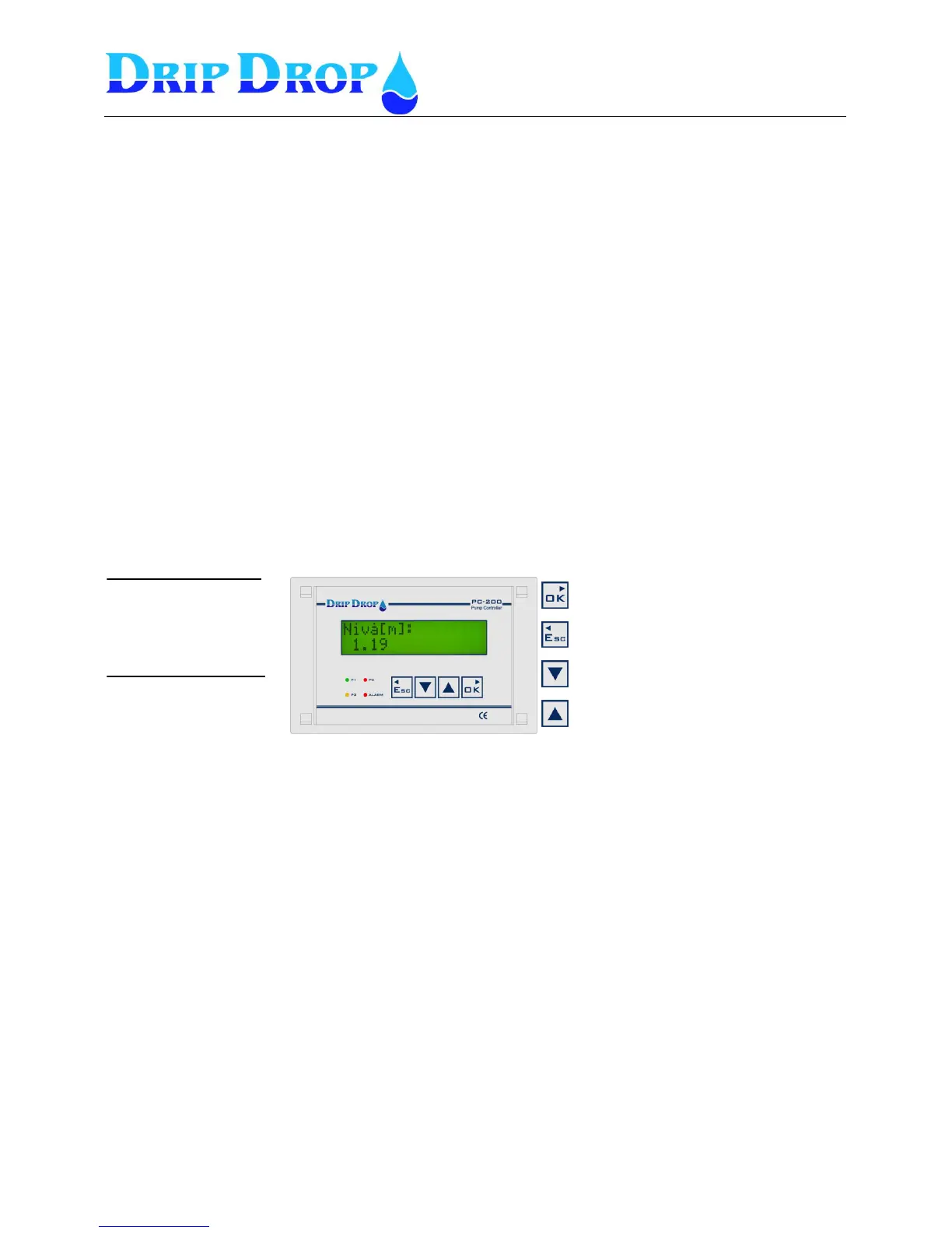
1.2 Operator unit
The operator unit is mounted in the front door of a cabinet and has 4 control keys for handling,
configuration and alarm. There are 4 light emitting diodes for indication of alarms and status and an
alphanumeric display with 2 x 16 signs for displaying all information.
Front panel
2 Log in – Access code
For looking at information about pumps, running times or alarm you can go directly to the actual
information menus. But to make changes or acknowledge alarms a.s.o. you need to enter an access
code depending of what you want to do. The unit is delivered with two different access codes:
1. Operator code – allows acknowledgement of alarms. The code is ZZZZ (▼▼▼▼)
2. System code – allows changes of for example start and stop values or configuration of the unit.
The code is 0000 (▲▲▲▲)
The access codes can be changed under ”System settings”
When you enter a menu and want to change any value, the access code prompt will show when you
press the OK key to enter the changing position. When the prompt shows up you set the actual code
and accept with the OK key you enter the changing position and can make the changes you desire.
The unit will automatically log out 5 minutes after the last time you pressed a key.
If the function “Trusted logged in” is activated no log out will be made.
Confirm choice, enter submenus, and to go
from the start menu to the main menu.
Exit the menus and go to the left.
Used to step downwards in the submenus, and
to change values to be set.
Used to step upwards in the submenus and to
change the values to be set.
Indication diode ”P1-P3”
3 multicolour diodes show the
status for each pump.
¤ Green shows pump is running.
¤ Red shows pump alarm
¤ Orange shows pump ”Not Auto”
Indication diode ”Alarm”
1 red diode shows the alarms.
¤ Red ”blinking” not ackn. alarm.
¤ Red ”fixed” active, ackn. alarm.