25
VAPOR-LOGIC
®
VERSION 6 INSTALLATION AND OPERATION MANUAL
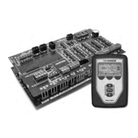
Terminal P15:
24vac = Power to combustion air switch
CAsw = Combust. air sw. (24vac input)
24vac = Power to power vent switch
PVsw = Power vent switch (24vac input)
Terminal
P15
AREA-TYPE AND SDU DISPERSION FANS
Connect wiring for Area-type and Space Distribution Unit (SDU) dispersion fans
by inserting the wire into the terminal block plug at P16 (labeled SDU). Tighten
screws.
OPTIONAL COMBUSTION AIR SWITCH AND POWER VENT
Connect wiring for GTS combustion air switch and/or GTS power vent by
inserting wires into the terminal block plugs at P15 and P16. Tighten screws.
Remove shunt on J403 (combustion air) or J404 (power vent) if it is installed.
The combustion air switch is on the combustion air damper. The power vent
switch indicates airflow at the power venter.
INSTALLATION
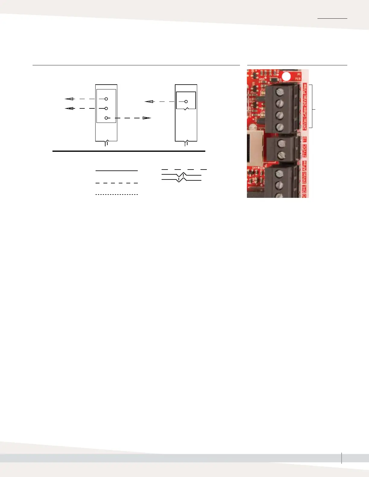
Key
Control circuit wiring
Field wiring
Optional factory
Optional field
Break to external
connections diagram
Contacts rated 125
VAC/3 AMP or 30
VDC/3 AMP, optional
by others
Vapor-logic relay #1 Vapor-logic relay #2
P12
P16
Normally open #2
Normally open #1
Common #1
Common #2
Step 1 – Field wiring
FIGURE 25-1: VAPOR-LOGIC PROGRAMMABLE RELAY WIRING CONNECTIONS FIGURE 25-2: TERMINAL P15