24
VAPOR-LOGIC
®
VERSION 6 INSTALLATION AND OPERATION MANUAL
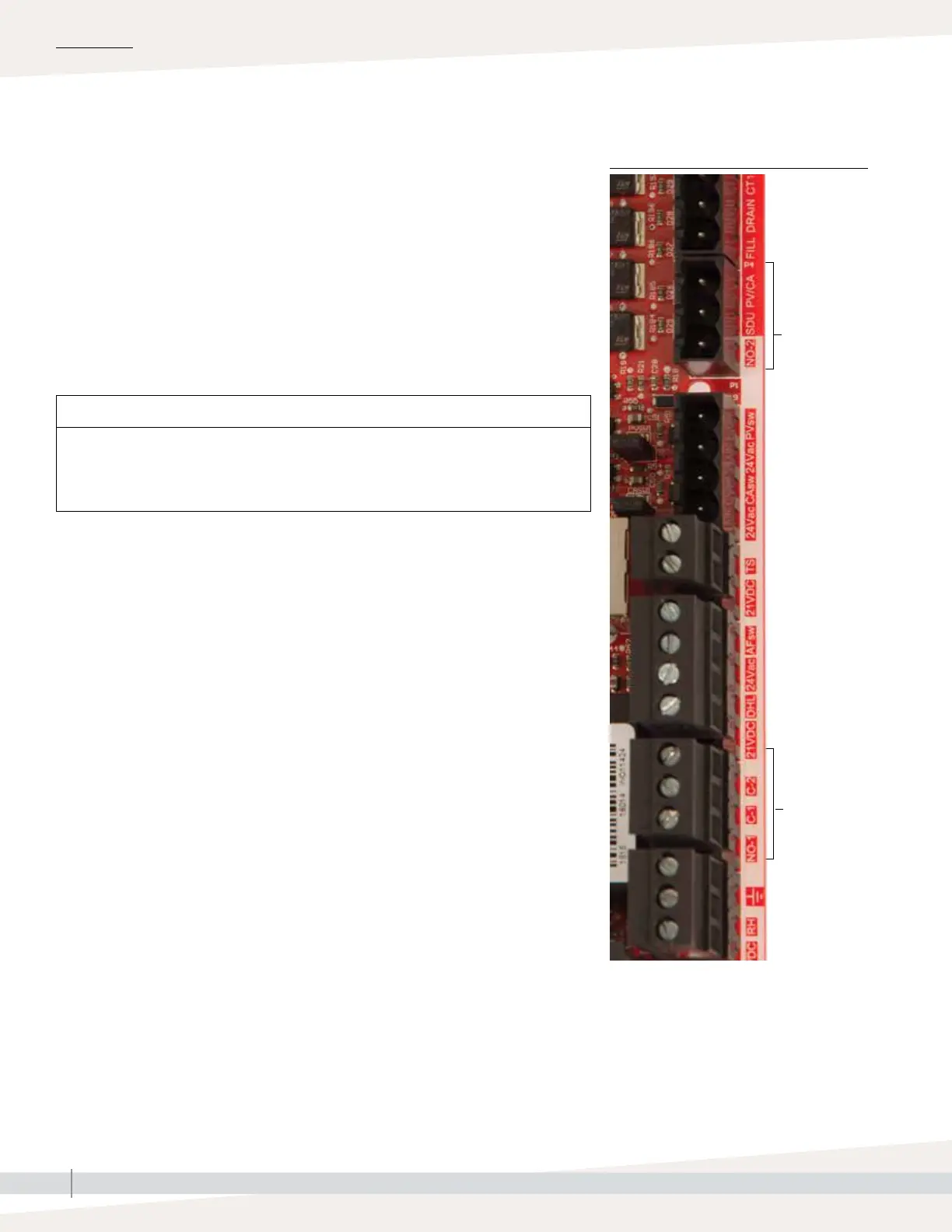
Terminal
P12
Terminal P12:
Programmable relay (dry contact)
NO-1 = Relay 1, normally open
C-1 = Common 1
C-2 = Common 2
Terminal
P16
Terminal P16:
NO-2 = Relay 2, normally open
PV/CA = Power vent/combustion air control
signal (24 vac output)
SDU = Space Distribution Unit (24 vac output)
PROGRAMMABLE RELAYS (DRY CONTACT)
See “Programmable relay maximum current” in Caution below.
See Figure 25-1. Connect wiring for remote signaling using a
programmable relay (dry contact) by inserting wires into the terminal block
plug at P12 or P16, per the wiring diagram in Figure 25-1. Tighten screws.
This connection allows remote activation of devices such as fans or signal
lights. Output parameters are defined during Step 2 of the installation process.
INSTALLATION
CAUTION
Programmable relay maximum current
Programmable relay (dry contact) (P12) is rated for 125 VAC, 3 AMP or 30 VDC, 3
AMP maximum. Exceeding this maximum rating can cause the relay component or
the Vapor-logic board to fail.
Step 1 –
FIGURE 24-1: TERMINAL P12 AND P16
Field wiring