■■■■■■■■■■■■■■■■■■■■■■■■■■■■■■■■■■■■■■■■■■■■■■■■■■■■■■■■■■■■■■■■■■■■■■■■■■■■■■■■■■■■■■■■■■■■■■■■■
▼
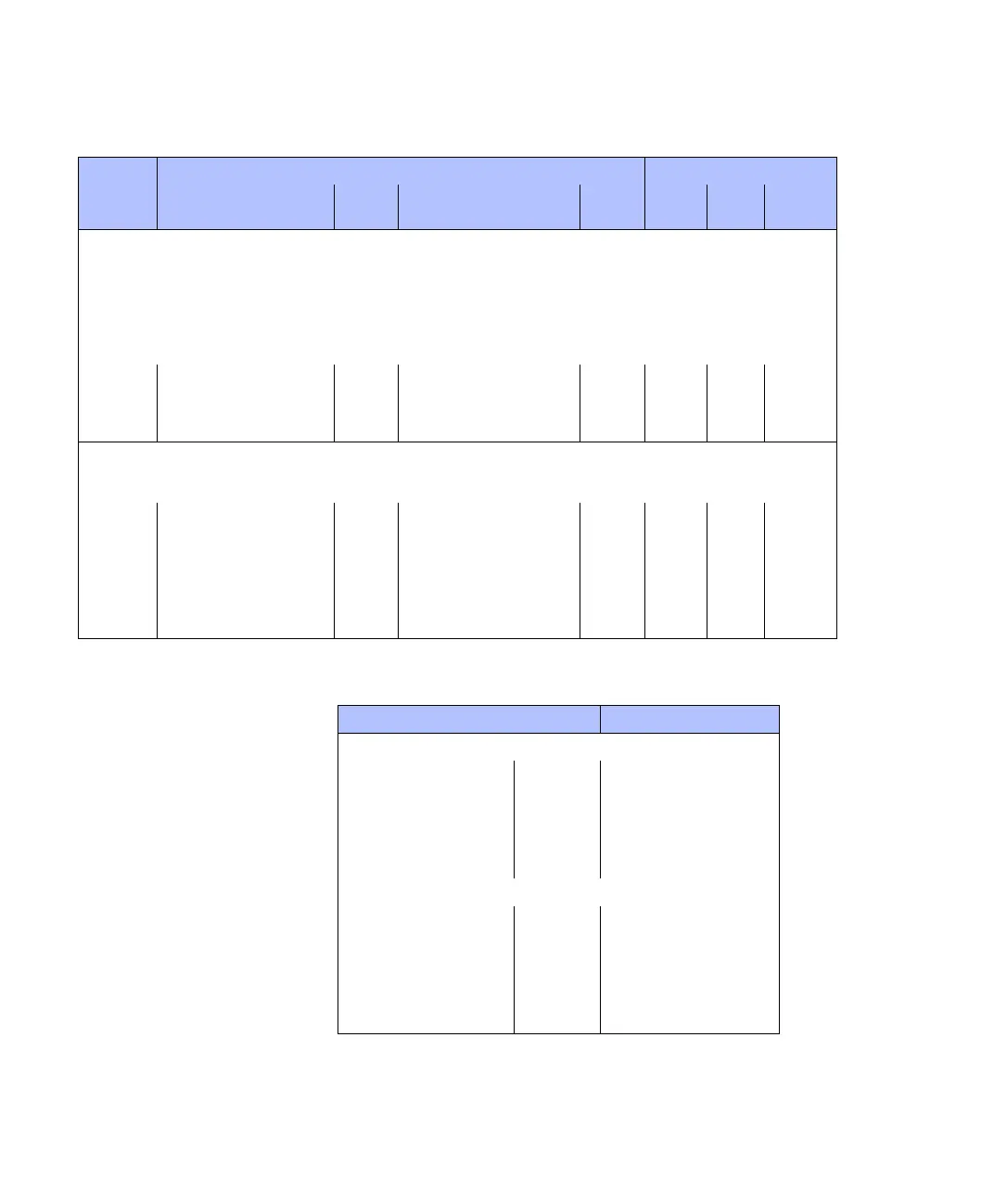
Mapping of I/O Signals
DS1104 Hardware Installation and Configuration March 2004
107
▲
■■■■■■■■■■I
▲■■■■■■■■■■■■■■■
GND pins The following I/O pins provide GND potential:
GND of the DS1104 is internally connected to PC ground.
Slave DSP Serial Peripheral Interface (SPI)
• TTL voltage range
• Output current range: ±13 mA
• SSOMI: SPI slave out, master in
• SSIMO: SPI slave in, master out
• SSTE: SPI slave transmit enable
• SSCLK: SPI clock
• I/O circuit and further electrical characteristics: see Slave DSP Digital I/O on page 142
SSOMI * – See Slave DSP Serial Peripheral
Interface in the DS1104 RTLib
Reference
P1 11 P1B 19 CP18 34
SSIMO * – P1 13 P1B 3 CP18 16
SSTE * – P1 15 P1B 36 CP18 35
SSCLK * – P1 17 P1B 20 CP18 17
User Interrupts
• TTL input voltage range
• I/O circuit and further electrical characteristics: see Bit I/O on page 125
IO16 * DS1104MASTER_HWINT_Ix User
int 1
See Interrupt Handling in the
DS1104 RTLib Reference
Ext int 0 P1 52 P1A 42 CP17 32
IO17 * User
int 2
Ext int 1 P1 51 P1B 42 CP17 14
IO18 * User
int 3
Ext int 2 P1 50 P1A 9 CP17 33
IO19 * User
int 4
Ext int 3 P1 49 P1B 9 CP17 15
Signal
Channel/Bit Numbers of Related RTI Blocks/RTLib Functions I/O Pin on …
Related RTI Block(s)
Ch/Bit
(RTI)
Related RTLib Functions
Ch/Bit
(RTLib)
DS1104
Sub-D
Conn.
CP/CLP
Connector Pin
DS1104
I/O Connector P1 1, 2, 33, 34, 47, 48, 69, 70,
73, 74, 77, 78, 81, 82, 85, 86,
89, 90, 93, 94, 97, 98
Sub-D Connector P1A 1, 13, 15, 17, 25, 30, 32, 39,
45, 47, 49
P1B 1, 13, 15, 17, 25, 30, 32, 39,
45, 47, 49
CP1104/CLP1104 Connector Panel
BNC CP1 … CP16 Shell
Digital I/O CP17 1, 4, 7, 10, 13, 16 … 19, 22,
25, 28, 31, 34, 35
Slave I/O CP18 1, 4, 6, 12 … 15, 20, 25,
30 … 33, 36, 37
Incremental Encoder Interface CP19, CP20 8, 10 … 15
UART RS232 and RS485/422 CP21 , CP22 5