Pressure supply
168 Service Instructions 745-35-10 S/745-35-10 A - 02.0 - 04/2017
If display reads S11+:
• Turn the screw (2) counterclockwise until the display reads S11-.
5. Exit Multi test I/O.
6. Pull up the pressure controller (4) and turn it until the pressure level is
at 6 bar.
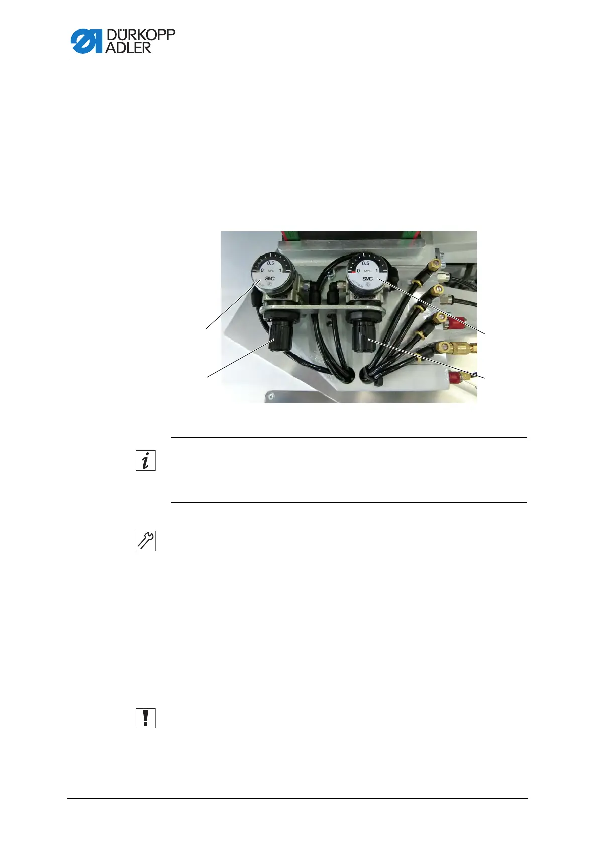
15.2 Setting the transport clamp control
Fig. 150: Setting the transport clamp control
Information
The downforce pressure can be adjusted separately for the right and the
left transport clamp depending on the type and thickness of the material.
To adjust the transport clamp control:
1. Turn the left pressure controller (2) to adjust the downforce pressure
of the transport clamp on the left.
The default setting is 0.5 Mpa = approx. 5 bar.
• Increase pressure: turn counterclockwise
• Reduce pressure: turn clockwise
2. Turn the right pressure controller (3) to adjust the downforce pressure
of the transport clamp on the right.
The default setting is 0.5 Mpa = approx. 5 bar.
• Increase pressure: turn counterclockwise
• Reduce pressure: turn clockwise
Important
The safe transport of the sewing material needs to be ensured at all times.
(1) - Pressure gage, left
(2) - Pressure controller, left
(3) - Pressure controller, right
(4) - Pressure gage, right
 Loading...