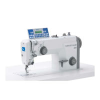
Machine head
Service Instructions 745-35-10 S/745-35-10 A - 02.0 - 04/2017 27
6. Insert the gage (13) with its pins into the locating bore (10).
7. Turn the crank pin (8) such that it meshes with the cutout of the
gage (13).Press on the crank pin (8).
The axial play of the thread lever (11) must be minimal to allow for oiling.
8. Tighten the screw (9).
9. Tighten the hexagon screws (14).
10. Remove the gage (13).
11. Turn the handwheel and check the arm shaft for ease of movement (12).
12. Slip the needle bar connecting rod together with the needle cage (8)
onto the crank pin.
13. Tighten the fastening screws firmly (Caution: Left-handed thread).
14. Assemble and adjust the needle bar linkage ( p. 38).
15. Assemble the switching cylinder used for the middle knife drive ( p. 61).
 Loading...