222
222
222
222
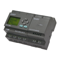
Communication
Communication
Communication
Communication
module
module
module
module for
for
for
for ELC-1
ELC-1
ELC-1
ELC-1 8
8
8
8
CPU
CPU
CPU
CPU
ELC-RS485
ELC-RS485
ELC-RS485
ELC-RS485 ELC
ELC
ELC
ELC -Ethernet-DC
-Ethernet-DC
-Ethernet-DC
-Ethernet-DC ELC
ELC
ELC
ELC -Ethernet-AC
-Ethernet-AC
-Ethernet-AC
-Ethernet-AC ELC-SMS-D-R
ELC-SMS-D-R
ELC-SMS-D-R
ELC-SMS-D-R
Input/supply voltage 12-24V DC 12-24V DC 110-240V AC 12-24V DC
Description isolated 485
converter,used
to bring out the
terminals of
RS485 port
built-in ELC-12
series CPU for
connection with
third party
devices.
Ethernet module
connecting to ELC-12
CPU units
,
DC type.
Ethernet module
connecting to ELC-12 CPU
units
,
AC type.
GSM/SMS module connecting to
ELC-18 CPU units( 6I/4O+ 10
message IO)
Connection cables 2 x 1.5 mm ² or 1 x 2.5 mm ²
Ambient
temperature
0 to + 55 º C
Storage temperature – 40 º C to + 70 º C
Degree of protection IP20
Certification CE
Mounting On 35 mm standard mounting rail, 4 MW, or wall-mounting
Dimensions W x H x D ( 72 x 90 x 53 mm)
Extensions
Extensions
Extensions
Extensions Units
Units
Units
Units (IO)
(IO)
(IO)
(IO) for
for
for
for
ELC-18
ELC-18
ELC-18
ELC-18 CPU
CPU
CPU
CPU
ELC
ELC
ELC
ELC -E
-E
-E
-E -
-
-
- 16
16
16
16 AC-
AC-
AC-
AC-
R
R
R
R
ELC-
ELC-
ELC-
ELC- E-16
E-16
E-16
E-16 DC-D
DC-D
DC-D
DC-D
-R
-R
-R
-R
ELC
ELC
ELC
ELC -E
-E
-E
-E -
-
-
- 16
16
16
16 DC-D
DC-D
DC-D
DC-D A
A
A
A
-
-
-
- R
R
R
R
ELC
ELC
ELC
ELC -E
-E
-E
-E -
-
-
- 16
16
16
16 DC-D-T
DC-D-T
DC-D-T
DC-D-T N
N
N
N ELC
ELC
ELC
ELC -E
-E
-E
-E -
-
-
- 16
16
16
16 DC-D
DC-D
DC-D
DC-D A
A
A
A -T
-T
-T
-T N
N
N
N
Inputs 8 digital 8 digital 8 digital 8 digital 8 digital
of which can be used in analog
mode
none none 2 (0 to 10V) none 2 (0 to 10V)
Input/supply voltage 110-240V AC 12-24V DC 12-24V DC 12-24V DC 12-24V DC
Permissible range
with signal “ 0 ”
with signal “ 1 ”
Input current
85 ... 265 V
AC
100 ... 253 V
DC
max. 40 V AC
0.03 mA
min. 79 V AC ,
0.08 mA
10.8 V ... 28.8 V
DC
max. 3 V
DC ,1mA
min. 8 V DC , 1.5
mA
10.8 V ... 28.8 V
DC
max. 3 V DC ,
1mA
min. 8 V DC , 1.5
mA
10.8 V ... 28.8 V DC
max. 3 V DC , 1mA
min. 8 V DC , 1.5 mA
10.8 V ... 28.8 V DC
max. 3 V DC , 1mA
min. 8 V DC , 1.5 mA
Outputs 8relays
( Q1-Q4,3A,Q
5-Q8,10A
)
8 relays
( Q1-Q4,3A,Q5
-Q8,10A
)
8relay
( Q1-Q4,3A,Q5-
Q8,10A
)
8 transistors(NPN) 8 transistors(NPN)
Continuous current 10 A with
resistive load;
2 A with
inductive load
10 A with
resistive load;
2 A with
inductive load
10 A with
resistive load;
2 A with inductive
load
0.3 A 0.3 A
Short-circuit protection External fuse
required
External fuse
required
External fuse
required
External fuse
required
External fuse required
Switching frequency 2 Hz with
resistive load;
0.5 Hz with
inductive load
2 Hz with
resistive load;
0.5 Hz with
inductive load
2 Hz with
resistive load;
0.5 Hz with
inductive load
2 Hz 2 Hz
Connection cables 2 x 1.5 mm ² or 1 x 2.5 mm ²
Ambient temperature 0 to + 55 º C
Storage temperature – 40 º C to + 70 º C
Degree of protection IP20
Certification CE
Mounting On 35 mm standard mounting rail, 4 MW, or wall-mounting
Dimensions W x H x D ( 72 x 90 x 53 mm)