Do you have a question about the Easy xLogic and is the answer not in the manual?
Describes the xLogic SuperRelay as a universal logic module replacing PLCs, timers, relays.
Lists key features like display, keypad programming, function block diagram, and communication protocols.
Explains various communication modules like RS232, USB, Ethernet, and SMS for connectivity.
Explains the naming convention for ELC series main modules, detailing each component.
Details the naming convention for ELC-18 and ELC-12 CPU expansion modules.
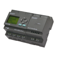
Illustrates the structure and component identification of ELC-18 and ELC-12 Series CPUs.
Step-by-step guide for mounting xLogic modules onto a DIN rail.
Instructions for wall-mounting xLogic devices using mounting slides and screws.
Details power supply requirements for AC and DC versions of xLogic modules.
Explains connecting sensor elements to xLogic inputs, including analog and digital.
Describes connecting loads to relay and transistor outputs, including current limits.
Introduces creating circuit programs for xLogic applications using xLogicSoft or directly on the unit.
Outlines four key rules: changing mode, inputs/outputs, cursor movement, and planning.
Guides on how to write a designed circuit program into the xLogic unit.
Introduces input and output blocks, describing their role in xLogic programs.
Lists simple logical elements like AND, NAND, OR, NOR, XOR, NOT used in circuit programs.
Lists available special function blocks (Timers, Counters, Analog, Miscellaneous) with their functions.
Covers activating Modbus Read for communication as a master via RS232/RS485.
Describes Proportional-integral controllers for controlling processes.
Guides on the initial screen display and navigation for xLogic HMI.
Guides on selecting and modifying parameters for function blocks.
Provides instructions for setting, modifying, and removing passwords for program protection.
Discusses requirements for stairway lighting systems and control methods.
Covers automatic gate applications in supermarkets, buildings, etc., and their requirements.
Details ventilation systems supplying fresh air and exhausting contaminated air, with sample system requirements.
Lists features of xLogicsoft: graphic interface, simulation, printing, saving, configuration, transfer, online test.
Step-by-step guide for installing xLogicsoft, including language selection and license agreement.
Explains testing the program, modifying parameters, and comparing calculations with actual behavior.
Provides technical specifications for ELC-18/12 Series Main Modules and Expansion Modules.
Provides detailed technical specifications for ELC-6, ELC-12, and ELC-18 series CPU units.
Illustrates switching capacity and service life curves for ohmic and inductive loads.
| Number of digital inputs | 8 |
|---|---|
| Protection class | IP20 |
| Input voltage range | 24 V DC |
| Operating temperature range | -25°C to +55°C |
| Storage temperature range | -40°C to +70°C |