EasyManua.ls Logo

Easy xLogic User Manual

Easy xLogic
226 pages
To Next Page IconTo Next Page
To Previous Page IconTo Previous Page
Page #36 background imageLoading...
Page #36 background image
34
34
34
34
C
C
C
C hapter
hapter
hapter
hapter 3
3
3
3 Programming
Programming
Programming
Programming xLogic
xLogic
xLogic
xLogic
Note
Note
Note
Note :
:
:
:
Only the new ELC-12 series &Upgraded ELC-18 CPU supports the programming via HMI panel key .
Getting
Getting
Getting
Getting started
started
started
started with
with
with
with xLogic
xLogic
xLogic
xLogic
Programming refers to creating a circuit program from the xLogic Basic module.
In this chapter you will learn how to use xLogic to create the xLogic circuit programs for your application.
xLogic Soft is the xLogic programming software that you can use on your PC to
quickly and easily create, test, modify, save and print the circuit programs. The topics in this manual,
however, relate only to the creation of circuit programs on the actual xLogic Basic module. The programming
software xLogic Soft contains extensive online help.
A small example in the first part of this chapter introduces the operating principles of xLogic :
You will learn the meaning of two basic terms, namely the connector and the block.
As the next step, you will create a circuit program based on a simple conventional circuit.
Lastly, you will enter this program directly in xLogic.
It will take you only a few pages of this manual to store your first executable circuit program in the xLogic unit.
With suitable hardware (switches etc.), you will then be able to carry out initial tests.
3.1
3.1
3.1
3.1 Connectors
Connectors
Connectors
Connectors
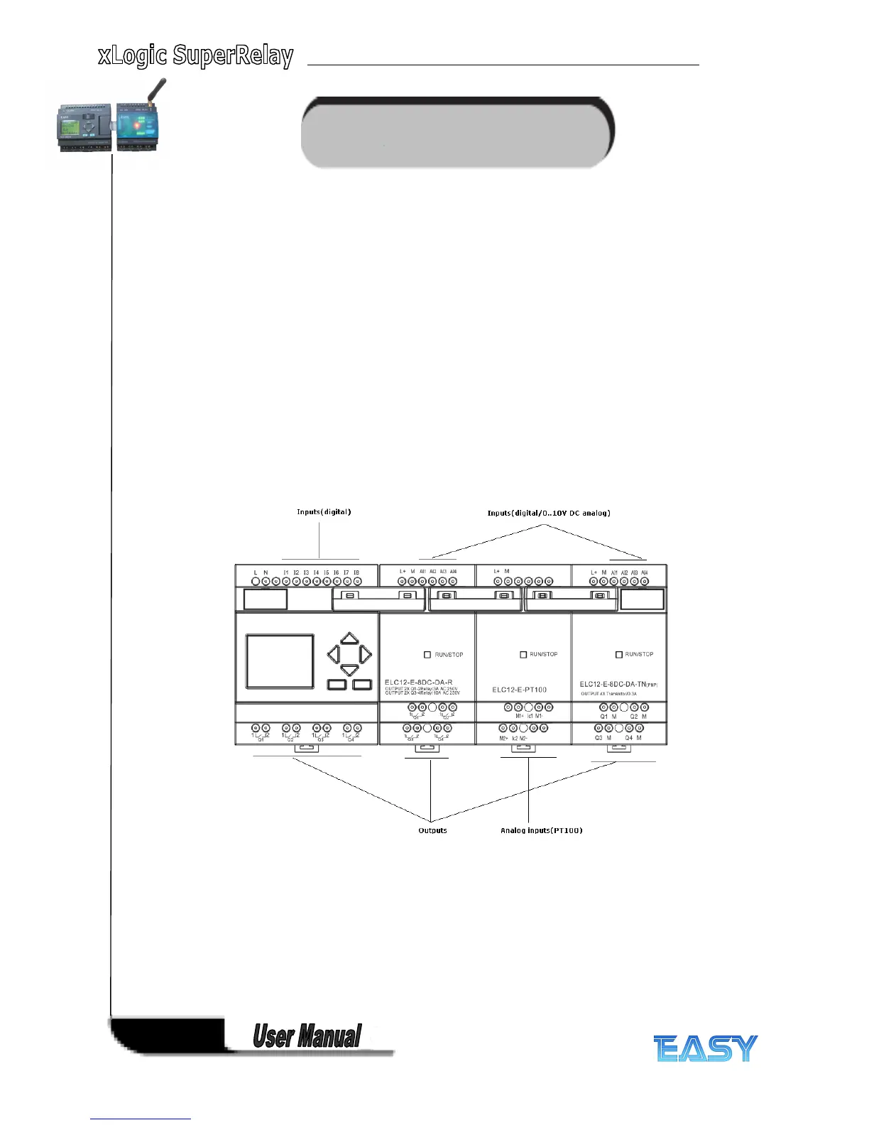
xLogic is equipped with inputs and outputs
Example of a configuration with several modules:
Each input is identified by the letter I plus a number. When you look at xLogic from the
front,you can see the input terminals at the top. Only analog modules (PT100 and 0 20mA
input ) have the inputs at the bottom.
Each output is identified by the letter Q plus a number ( ELC-E- AQ: AQ plus number). In the
figure, you can see the output terminals at the bottom.
Note
xLogic can recognize, read and switch the I/O of all expansion modules regardless of their type.
The I/Os are not presented in the installation order of the modules , it rests with the address of
the expansion modules . For example the first input of the expansion module with the
Question and Answer IconNeed help?

Do you have a question about the Easy xLogic and is the answer not in the manual?

Easy xLogic Specifications

General IconGeneral
Number of digital inputs8
Protection classIP20
Input voltage range24 V DC
Operating temperature range-25°C to +55°C
Storage temperature range-40°C to +70°C

Summary

Chapter 1 General Introduction to xLogic

Overview

Describes the xLogic SuperRelay as a universal logic module replacing PLCs, timers, relays.

Highlight Features

Lists key features like display, keypad programming, function block diagram, and communication protocols.

Communication modules

Explains various communication modules like RS232, USB, Ethernet, and SMS for connectivity.

Naming Rules of ELC Series

Model name (main module)

Explains the naming convention for ELC series main modules, detailing each component.

Model name (expansion module)

Details the naming convention for ELC-18 and ELC-12 CPU expansion modules.

Chapter 2 Installing/removing xLogic

Structure

Illustrates the structure and component identification of ELC-18 and ELC-12 Series CPUs.

DIN rail mounting

Step-by-step guide for mounting xLogic modules onto a DIN rail.

Wall-mounting

Instructions for wall-mounting xLogic devices using mounting slides and screws.

2.2 Wiring the xLogic

Connecting the power supply

Details power supply requirements for AC and DC versions of xLogic modules.

Connecting xLogic Inputs

Explains connecting sensor elements to xLogic inputs, including analog and digital.

Connecting xLogic Outputs

Describes connecting loads to relay and transistor outputs, including current limits.

Chapter 3 Programming xLogic

Getting started with xLogic

Introduces creating circuit programs for xLogic applications using xLogicSoft or directly on the unit.

The four golden rules for operating xLogic

Outlines four key rules: changing mode, inputs/outputs, cursor movement, and planning.

Writing and starting the circuit program

Guides on how to write a designed circuit program into the xLogic unit.

Chapter 4 xLogic functions

General Input & Output functions

Introduces input and output blocks, describing their role in xLogic programs.

Basic functions list – GF

Lists simple logical elements like AND, NAND, OR, NOR, XOR, NOT used in circuit programs.

Special functions list – SF

Lists available special function blocks (Timers, Counters, Analog, Miscellaneous) with their functions.

Modbus Read

Covers activating Modbus Read for communication as a master via RS232/RS485.

PI controller

Describes Proportional-integral controllers for controlling processes.

Chapter 5. Configuring xLogic

Instruction of xLogic-HMI

Guides on the initial screen display and navigation for xLogic HMI.

Set parameter

Guides on selecting and modifying parameters for function blocks.

Set password

Provides instructions for setting, modifying, and removing passwords for program protection.

Chapter 6. Application

Dual-function switch

Discusses requirements for stairway lighting systems and control methods.

Automatic gate

Covers automatic gate applications in supermarkets, buildings, etc., and their requirements.

Ventilation system

Details ventilation systems supplying fresh air and exhausting contaminated air, with sample system requirements.

Chapter 7 xLogic Software

xLogicsoft features

Lists features of xLogicsoft: graphic interface, simulation, printing, saving, configuration, transfer, online test.

Installing xLogicsoft(xLogic)

Step-by-step guide for installing xLogicsoft, including language selection and license agreement.

Program Testing

Explains testing the program, modifying parameters, and comparing calculations with actual behavior.

Appendix A Technical data

General technical data

Provides technical specifications for ELC-18/12 Series Main Modules and Expansion Modules.

Technical data: xLogic (ELC series)

Provides detailed technical specifications for ELC-6, ELC-12, and ELC-18 series CPU units.

Switching capacity and service life of the relay outputs

Illustrates switching capacity and service life curves for ohmic and inductive loads.

Related product manuals